Abstract
While integrating the MAX77972, I ran into a problem that was less obvious than I expected: the same symptom could come from the charger, the USB source limit, the battery model, or the way firmware accessed the registers. A low measured current did not necessarily mean that the current setting was wrong. Likewise, a precise-looking percentage could still be far from the battery's real state.
I therefore decided to collect the parts that matter during bring-up in one guide: architecture, initialization, I2C access, AICL, temperature handling, ModelGauge m5, state decoding, and recovery. The goal is not to list registers, but to build a debugging method that explains why the device reached a particular state before trying to change it.
The MAX77972 from Analog Devices, originally from the Maxim Integrated line, is a PMIC for products powered by a single Li-ion or Li-poly cell. It integrates a buck charger with FETs, a ModelGauge m5 fuel gauge, USB Type-C and BC1.2 detection, power-path management, reverse boost/OTG, and several hardware protections.
On paper, it looks like the kind of chip that "does everything." That is precisely why it requires discipline: hardware, firmware, and the battery model must agree. Otherwise, the most common symptoms are these:
- charging does not start
- charging starts and then stops
- measured current is far lower than the configured current
- the battery still discharges while USB is plugged in
- battery percentage gets stuck
- SOC jumps, collapses, or sits at 99%
- THM temperature is implausible
- charger state is decoded without enough context
The most useful mental model, in my experience, is simple: the MAX77972 is not a passive charger. It is a small power system with internal state, volatile RAM, 16-bit registers, automatic input limits, and a fuel-gauge algorithm. Treating it as "a few registers to write once" eventually leads to a state that is difficult to explain.
The datasheet describes the MAX77972 as an autonomous charger with integrated fuel gauge, USB Type-C and BC1.2 detection, a 4.5 V to 13.7 V input range, and up to 3.15 A charge current. The fuel gauge uses ModelGauge m5, which combines coulomb counting and a voltage-based model, while charging is coordinated with 9-region JEITA and step charging.
Let us therefore look at how to integrate the device and, more importantly, how to interpret it when the observed behavior does not match the expected one.
What the MAX77972 integrates
The MAX77972 contains four main blocks.
| Block | What it does |
|---|---|
| Buck charger | handles precharge, trickle, CC, CV, top-off, termination, and restart |
| ModelGauge m5 fuel gauge | estimates SOC, capacity, current, remaining time, cycles, and aging |
| USB detection | detects Type-C current advertisement and BC1.2 sources |
| Power path | supplies SYS, charges BATT, and lets the battery supplement the system |
The charger supports an operating input up to 13.7 V and up to 3.15 A charge current, always within the thermal and layout limits of the product. Charge current and voltage can be configured through I2C or resistors.
The ModelGauge m5 fuel gauge combines voltage measurement, coulomb counting, and a cell model. That is powerful, but it has a consequence: if the model does not represent the actual battery used in the product, the displayed percentage can look precise while being wrong.
USB detection lets the chip identify SDP, CDP, DCP, and a USB-C source advertising 500 mA, 1.5 A, or 3 A. The chip can then set the input current limit automatically. The datasheet says the MAX77972 runs D+/D- detection and CC detection in parallel, then selects the highest supported limit from the detected source.
The power path is often underestimated. With USB attached, the system can be powered from SYS/BYP while the battery charges. If the system load consumes more than the USB source can provide, the battery can supplement the system. So "USB plugged in" does not automatically mean "battery percentage going up."
USB Type-C does not automatically mean USB Power Delivery
USB-C is one of the most common sources of confusion.
The MAX77972 detects the advertised current on CC1/CC2 and supports BC1.2 detection on D+/D-. That is enough for many products powered from 5 V.
It is important, however, to distinguish those features from actual USB Power Delivery negotiation. The device documentation describes Type-C current and BC1.2 detection, but not a policy engine or Power Data Object exchange. In practice, the MAX77972:
- it does not negotiate PDOs
- it does not implement a USB-PD policy engine
- it does not request higher-voltage profiles by itself
- it does not replace a PD controller when real negotiation is required
If the product only needs to charge from 5 V, the chip may therefore be sufficient. If the architecture requires higher-voltage PD profiles, it needs an external controller or a different topology. This sounds like a small distinction, but it is fundamental when sizing the source, connector, and firmware.
Practical architecture

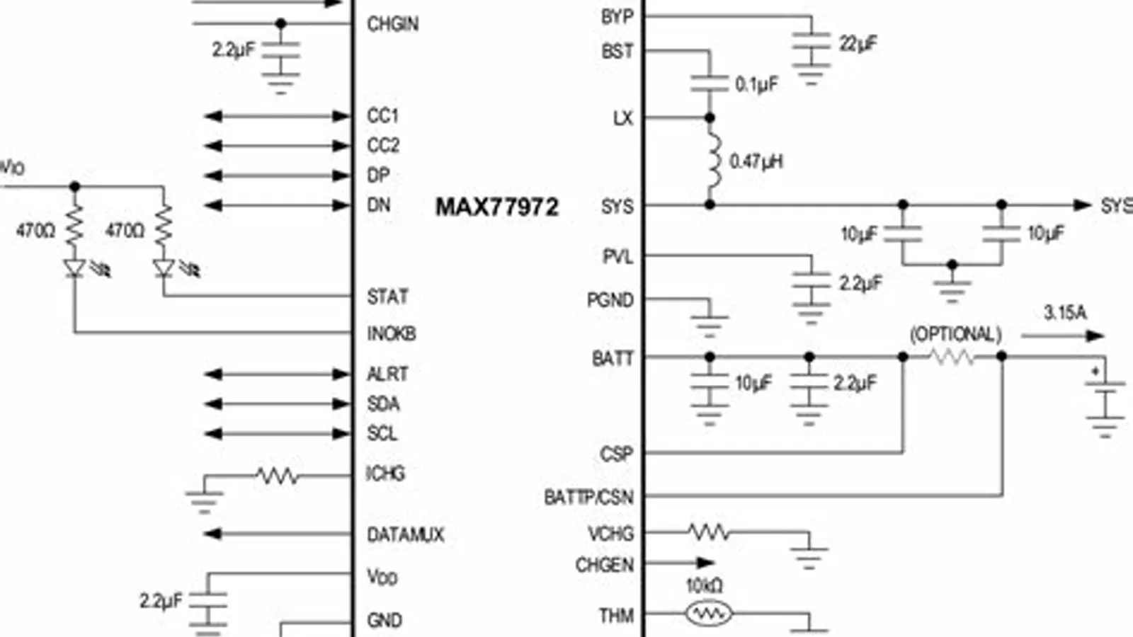
The MAX77972 sits between the USB source, the system, the battery, and firmware. Real issues almost always come from interactions between those blocks.
A typical integration has these connections:
- USB input to
CHGIN SYSorBYPto the system load- cell on
BATT - current sense path that matches the hardware
CC1andCC2to the USB-C connectorDPandDNfor BC1.2, if usedTHMto the battery thermistor, or an alternative temperature configuration- I2C to the microcontroller or application processor
CHGENcontrolled by firmware or external logicALRTandSTATas interrupt/status signals
This architecture explains why debugging must be systemic. Reading ChargingCurrent and concluding "the chip is not charging" is not enough. Check the input, USB limit, AICL, temperature, charger state, measured current, cell voltage, and system load.
Critical pins and nodes
The main nodes are:
| Node | Role |
|---|---|
CHGIN | USB or adapter input |
BYP | power-path and reverse-boost node |
SYS | system supply |
BATT | cell connection |
LX | buck switching node |
CSP/CSN | battery-current sensing |
THM | battery thermistor input |
CC1/CC2 | USB Type-C detection |
DP/DN | BC1.2 detection |
CHGEN | charger enable or disable |
STAT | open-drain status output |
ALRT | open-drain alert output |
INOKB | valid-input indication |
DATAMUX | configurable pin for reset/pushbutton and USB data-mux behavior |
CHGIN, BYP, SYS, BATT, LX, and power ground are not ordinary signals. They are power or switching nodes. Layout must reduce current loops, voltage drops, and noise coupled into THM, CSP/CSN, and I2C.
Pay attention to DATAMUX: with its default configuration, the pin participates in the pushbutton-reset function for SYS. Setting nChgConfig4.DATAMUX to 1 enables the USB data mux and disables that reset function. It should not be treated as a generic pin without checking both the schematic and the configuration.
The official EV kit is useful not only for evaluating the chip, but also as a reference for the schematic, layout, and configuration sequence. Its guide describes an assembled and tested board with an integrated I2C interface and a Windows application. It is not a schematic to copy blindly, but it provides a useful comparison during bring-up.
Charge cycle
The charge cycle is classic, but guarded by several automatic protections.
| Phase | What happens |
|---|---|
| Precharge | very low battery, limited current |
| Trickle | controlled early charge |
| Fast CC | constant current, if input and temperature allow it |
| Fast CV | constant voltage, current falls over time |
| Top-off | completion near the termination threshold |
| Done | charge terminated, with restart depending on battery voltage |
This explains a common debugging mistake: if you configure 2 A and measure 300 mA, the register is not necessarily wrong.
Possible causes:
- the battery is already in CV mode
- the USB source cannot provide the requested current
- AICL reduced the input limit
- the chip is in thermal foldback
- JEITA reduced or suspended charging
- the system consumes a large part of the available current
- current sensing is configured incorrectly
The driver must always distinguish programmed charge current from actual measured current. They are different pieces of information. The datasheet lists fast-charge CV, input current limit, AICL, and thermal foldback as reasons why actual current can be lower than ChargingCurrent.
AICL: the most common "stuck charge" case
AICL, Adaptive Input Current Limit, is one of the chip's most important functions and one of the first things I check when charging appears to stop without an obvious reason.
It prevents a weak USB source from collapsing when the device tries to draw too much current. If CHGIN drops below the configured threshold, the MAX77972 reduces the input current limit. If the source is too weak, charging can be disabled.
In debug this is often read as "the charger stopped." In reality, the chip is protecting the system.
| Symptom | Possible cause | Useful check |
|---|---|---|
| charging starts and then stops | CHGIN collapses | read CHGIN_OK, CHGIN_DTLS, AICL_OK |
| actual current below target | AICL or USB limit | read input limit and average current |
| PC charges poorly, wall adapter is fine | SDP or low input limit | verify BC1.2 and Type-C detection |
| battery drops while USB is attached | SYS consumes more than the source provides | compare system load and input limit |
| bench supply stays at 500 mA | detection did not identify a stronger source | use manual input limit only in controlled tests |
The datasheet says AICL automatically reduces current to keep CHGIN at the VCHGIN_REG regulation threshold, 4.5 V by default. If the input limit falls to 60 mA and the charger remains in the AICL loop, the charger is turned off.
The practical rule is this: do not force 3 A just because the product can charge at 3 A. If the source cannot supply it, the result will be AICL, input collapse, or intermittent charging.
USB detection and input current limit
The MAX77972 can work in automatic or manual mode.
In automatic mode:
- it reads CC1/CC2 to infer the current advertised by a USB-C source
- it runs BC1.2 on D+/D- when applicable
- it chooses an input limit consistent with the detected source
- if the source is not recognized, it uses a conservative value
In manual mode:
- firmware disables automatic input-current setting
- firmware writes the input current limit directly
- bench tests become more repeatable
- firmware takes responsibility for not asking too much from the source
The datasheet says automatic input-current limit is enabled by default. To set it manually, firmware must write nChgConfig4.NO_AUTOISET = 1 and then configure nChgConfig3.CHGIN_ILIM.
Manual input limit is convenient in the lab, but risky in production. If a PC port is treated like a 3 A adapter, the chip will do what it should: limit, suspend, or make charging intermittent.
JEITA, THM, and temperature
The chip supports multi-region JEITA temperature behavior. Temperature can come from the external thermistor on THM, the internal die temperature, or an external value written through I2C, depending on configuration.
If THM reads an impossible temperature, the charger can reduce or suspend charging.
Minimum checks:
- are
TempandAvgTAplausible? - does the configured THM pull-up match the hardware?
- does the selected temperature source match the design?
- are the JEITA thresholds consistent with the product requirements?
- are I2C transactions complete and clean?
- is
THMrouted away from noisy nodes?
There is a public EngineerZone case where THM readings jumped to 127.9 °C and charging was suspended. The author later traced the issue to SCL being held low by the master when the I2C thread was interrupted by a higher-priority task. This is not an officially documented device erratum, but it is consistent with one important fact: the MAX77972 does not use clock stretching and, according to the datasheet, does not hold SCL low.
This does not mean every THM problem has the same cause. But the lesson is concrete: transactions to the MAX77972 must be atomic, complete, 16-bit where required, and not interrupted halfway through.
I2C and 16-bit registers
One of the most important rules is this: do not treat fuel-gauge registers as 8-bit registers.
The chip exposes two main I2C areas:
| 7-bit address | Typical area |
|---|---|
0x36 | low memory, 0x000-0x0FF |
0x37 | high memory, 0x180-0x1FF |
The register pointer is 8 bit, but the logical register can live in two different spaces. The 0x100-0x17F interval belongs to neither window: mapping it automatically to 0x37 would turn a caller error into an access to a different register.
For that reason, I prefer to validate the register number, I2C address, and pointer in one place:
#define MAX77972_I2C_FUNC 0x36#define MAX77972_I2C_DEBUG 0x37static int max77972_map_reg(uint16_t reg, uint8_t* addr, uint8_t* ptr) { if (reg <= 0x0ff) *addr = MAX77972_I2C_FUNC; else if (reg >= 0x180 && reg <= 0x1ff) *addr = MAX77972_I2C_DEBUG; else return -EINVAL; *ptr = (uint8_t)(reg & 0xff); return 0;}For word registers, writing one byte is a bug. The Software Implementation Guide specifies that the FG_FUNC and FG_DEBUG areas use a 16-bit word size: an attempt to modify only 8 bits is discarded by the I2C logic.
In real debugging, use write-and-verify:
- write the 16-bit word
- read the word back
- verify mask and value
- retry only a limited number of times
- if it still fails, report an error instead of continuing with uncertain state
Example:
int max77972_write16(struct max77972* m, uint16_t reg, uint16_t val) { uint8_t addr; uint8_t ptr; int ret; ret = max77972_map_reg(reg, &addr, &ptr); if (ret) return ret; uint8_t buf[3] = { ptr, (uint8_t)(val & 0xff), // LSB (uint8_t)((val >> 8) & 0xff) // MSB }; return i2c_write(addr, buf, sizeof(buf));}int max77972_update_bits16(struct max77972* m, uint16_t reg, uint16_t mask, uint16_t value) { uint16_t oldv; uint16_t newv; int ret; ret = max77972_read16(m, reg, &oldv); if (ret) return ret; newv = (oldv & ~mask) | (value & mask); if (newv == oldv) return 0; ret = max77972_write16(m, reg, newv); if (ret) return ret; return max77972_verify_bits16(m, reg, mask, value);}Bus frequency also matters. The datasheet specifies a range from 20 kHz to 400 kHz and states that the chip does not use clock stretching. The master must therefore stay within that range, use pull-ups suitable for the bus capacitance, and complete each transaction without leaving SCL low because of preemptible bit-banging or competing tasks.
Correct conversions
Many bugs come from wrong conversions, wrong signedness, or current scale that does not match the sense resistor.
Common conversions:
| Quantity | Conversion |
|---|---|
RepSOC | raw / 256 percent |
RepCap | raw * 0.5 mAh |
FullCapRep | raw * 0.5 mAh |
VCell | raw * 78.125 µV |
Current | int16(raw) * 0.15625 mA, with 10 mΩ sense |
Temperature | int16(raw) / 256 °C |
Cycles | raw * 25% = raw / 4 cycles |
The Cycles conversion is easy to get wrong. In the datasheet, the Cycles register has a scalar of 25.0 and percentage units: one full cycle is 100%, so 4 LSBs correspond to one cycle. To get the number of cycles, use raw / 4, not raw / 100.
Example:
static float repsoc_percent(uint16_t raw) { return raw / 256.0f;}static float repcap_mah(uint16_t raw) { return raw * 0.5f;}static float vcell_mv(uint16_t raw) { return raw * 0.078125f;}static float current_ma(uint16_t raw) { return (int16_t)raw * 0.15625f;}static float temperature_c(uint16_t raw) { return (int16_t)raw / 256.0f;}static float cycles_count(uint16_t raw) { return raw / 4.0f;}If the product uses a sense resistor that does not match the configured scale, the entire current side becomes suspicious. That affects charging, termination, coulomb counting, learning, and step charging.
The simplest choice, when possible, is an external 10 mΩ sense resistor configured exactly as expected.
Internal or external current sense
The MAX77972 can use an internal sense equivalent to 10 mΩ or an external sense resistor. The datasheet says nADCCfg.RsnsEn = 0 selects internal sense, while RsnsEn = 1 selects external sense; for the latter, it recommends 10 mΩ. The Current register has a 0.15625 mA/LSB scale referred to 10 mΩ.
The Software Implementation Guide clearly separates the two cases:
| Configuration | Setting |
|---|---|
| Internal sense | CGTempCo = 0x0022 |
| External sense | nADCCfg.RsnsEn = 1 and CGTempCo = 0x0000 |
This part is critical. If the hardware uses external sense but firmware leaves RsnsEn = 0, current is wrong. If the hardware uses internal sense but firmware uses external-sense parameters, current is wrong. And if current is wrong, SOC, capacity, learning, and termination can become wrong too.
ModelGauge m5: powerful, but not magic
The integrated fuel gauge is one of the main reasons to choose the MAX77972. It can report percentage, remaining capacity, full capacity, current, voltage, temperature, remaining time, cycles, and aging.
Important registers:
| Register | Main use |
|---|---|
RepSOC | user-facing battery percentage |
RepCap | reported remaining capacity |
FullCapRep | full capacity used for RepSOC |
FullCapNom | learned nominal capacity |
DesignCap | configured nominal capacity |
VEmpty | empty threshold |
IChgTerm | termination current |
ModelCfg | model configuration |
QH | raw coulomb count |
SOCHold | 99% hold and near-empty hold behavior |
For a normal UI, show RepSOC. Internal values like VFSOC, MixSOC, or AvSOC are useful for debugging, but they only tell part of the story. The datasheet describes RepCap / RepSOC as ModelGauge m5 outputs together with the other capacity and SOC registers.
The delicate part is the cell model. The chip does not automatically know the actual battery. If you use EZ Config, the OCV-vs-SOC model is generic. If the cell's curve is far from that generic curve, ModelGauge m5 can converge toward the wrong result.
Initialization sequence
The Software Implementation Guide is clear: when power is applied or restored, firmware must initialize the chip. Many recommended registers live in RAM and must be rewritten after POR.
A robust sequence is:
- validate hardware configuration and product profile
- drive
CHGENlow - wait until
FSTAT.DNR = 0 - unlock extended registers when needed
- read
Status.PORandBAT_dis_OC - if full init is needed, handle dead battery before model load
- load the cell INI or EZ Config
- configure current sense, JEITA, AICL, voltage, current, timer, and Type-C detection
- clear latches only after understanding why they were active
- drive
CHGENhigh - lock registers if the product policy requires it
- take an immediate diagnostic snapshot
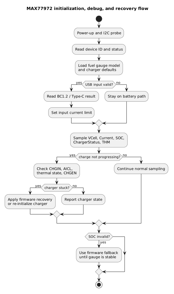
A reliable driver separates initialization, sampling, classification, and recovery. Jumping straight to reset often makes the problem harder to understand.
The official guide says to start with CHGEN low, wait for FSTAT.DNR = 0, check POR and battery over-discharge, load one of the three battery configuration flows, and then enable charging by driving CHGEN high.
For dead battery, the guide describes bringing the cell to a minimum voltage before completing fuel-gauge initialization. The official threshold in the procedure is about 2.5 V. Product firmware can choose a more conservative threshold, but that should be documented as a product choice, not as a datasheet requirement.
EZ Config, Short INI, and Full INI
The MAX77972 can be configured in three ways:
| Method | When to use it |
|---|---|
| EZ Config | prototype or common battery, without an INI file |
| Custom Short INI | custom configuration without OCV table |
| Custom Full INI | best accuracy, with characterized OCV table |
With EZ Config, the guide writes DesignCap, IChgTerm, VEmpty, RepCap = 0, and then ModelCfg. After ModelCfg, firmware must wait until the Refresh bit returns to zero.
With Custom Short INI, the flow adds parameters such as LearnCfg, nRCOMP0, nTempCo, and QRTable.
With Custom Full INI, the model is written to locations 0x80 through 0x9F, then read back and verified. If a word does not match, it must be rewritten. The guide also specifies loading FullCapRep, FullCapNom, RCOMP0, TempCo, Cycles, and other parameters, using saved history when available.
This is often what determines whether the SOC estimate is credible. If the real battery differs from the generic model, EZ Config may be sufficient for a prototype, but not necessarily for a product.
When the battery percentage is wrong
The more subtle problem, however, is often not charging. It is SOC.
In real debugging, behavior can look like this:
- the cell is physically close to full
VCellis around 4.10 V at rest- the real cell curve would say, for example, around 90%+
- the EZ Config model interprets the same voltage much lower
VFSOCstays near that wrong valueRepSOCsettles on a value that is difficult to reconcile with the physical state
This is not necessarily a conversion bug. It can be a model problem.
The correct solution is to load an INI characterized for the actual cell, obtained from the cell vendor or through dedicated characterization. That file contains tables and parameters consistent with the battery chemistry and measured curve.
Without that INI, every workaround is containment:
- do not save obviously corrupted learned capacity
- reject persisted data outside a physically credible range
- force full init if
FullCapNomorFullCapRepare out of bounds - be more cautious when
VFSOCand the coulomb counter diverge heavily - avoid hiding the issue by clearing only the visible symptom
- use firmware SOC based on
QHonly as a documented fallback
This distinction matters. If the OCV table is wrong, there is no magic register that fixes everything. You can contain the damage, but the real cure is the correct cell model.
99% Hold and Empty Hold
Two behaviors are easy to mistake for bugs.
The first is 99% Hold. If enabled, RepSOC does not go above 99% until a charge-termination event is detected. This avoids showing 100% before the battery has really reached end of charge.
The second is Empty Hold. It prevents the system from showing 0% or a percentage that is too low before the battery has actually crossed the configured empty threshold.
The datasheet says the MAX77972 supports both functions: 99% Hold limits RepSOC until charge termination, while Empty Hold prevents RepSOC from dropping below a threshold until voltage crosses VEmpty + EmptyVoltHold.
So:
- SOC stuck at 99% does not immediately mean bug
- SOC held near empty can be intentional
- before disabling
SOCHold, understand whether the product actually wants that behavior - if 100% never arrives, check termination,
IChgTerm, measured current, andProtStatus.Full
Workarounds tried: what helps and what does not
During product debugging, some ideas look right until you inspect long logs.
Forcing MIX_EN to zero
One temptation is disabling parts of the ModelGauge mixing path because it looks like the voltage-based estimate is damaging FullCapNom or RepCap when the OCV curve is wrong.
The problem is that MIX_EN does not control only one isolated detail. It affects how the algorithm combines different information sources. Disabling it outside the intended INI flow can stop one kind of collapse while introducing another, for example after unplug.
Important note: the Software Implementation Guide uses LearnCfg.MixEn in the Custom Full INI flow to control FullCapNom updates. That does not mean it is safe to use it as a permanent hack in any product. Follow the INI when you have it; if you deviate, document it and validate with complete logs.
Practical lesson:
- do not freeze parts of the algorithm without full charge and discharge logs
- do not validate only the "charge done" case
- always inspect the first 30-60 seconds after unplug
- separate temporary workaround from final configuration
Forcing HIB_CFG to zero
Another hypothesis is disabling hibernate, assuming hibernate convergence drags RepCap toward a wrong value.
This can be true in some cases, but it can also mislead you. If earlier firmware wrote the wrong address, the HIB_CFG write may never have had any effect. Fixing the address can make firmware behavior real and expose a problem that was previously only hidden.
Practical lesson:
- one fixed bug can reveal another bug
- if behavior changes after a register-address fix, do not assume the fix is wrong
- check whether two previous mistakes were cancelling each other out
Validating learned values
This is a sensible containment measure, provided that the limits are treated as product policy rather than values prescribed by Analog Devices.
Before trusting learned state, firmware can check whether FullCapNom and FullCapRep are inside a physically credible range relative to DesignCap.
An initial example, to be validated against cell tolerances, temperature, and aging, could look like this:
FullCapNombelow 0.5x design or above 1.5x design: suspiciousFullCapRepbelow 0.5x design or above 1.10x design: suspicious- NVS data outside the accepted range: reject it
- chip already corrupted at boot: force full init
- data consistent but old: restore it with diagnostic logging
These coefficients are deliberately illustrative. They do not make the OCV curve correct, but they prevent clearly corrupted state from surviving many boots. In a real product, the limits must be derived from the cell and from the margins the design can tolerate.
Updating nFilterCfg.MIX at the correct time
The Software Implementation Guide recommends updating nFilterCfg.MIX only after LearnStage has reached 0x7. Its stated purpose is to increase the voltage-gauge mixing rate after the expected learning sequence is complete.
It is important not to reverse the meaning of that recommendation: this is not a generic bias toward coulomb counting, nor is it a cure for an incorrect OCV model. Apply it at the point defined by the official flow or the INI, rather than moving it earlier in an attempt to repair an implausible SOC.
Firmware SOC based on QH
When the chip's SOC is not reliable, an alternative strategy is to use the MAX77972 as a coulomb sensor and compute percentage in firmware.
The key register is QH. The datasheet describes it as a raw coulomb count generated by the device and used internally as an input to the mixing algorithm. Monitoring its change over time is useful for debugging; the scale is 0.5 mAh/LSB with a 10 mΩ sense.
A fallback based on QH can therefore be built. It should be stated clearly, however, that this is not the official user-facing output represented by RepSOC. It is a firmware workaround that requires its own persistence and recalibration strategy.
Basic idea:
- read
QHperiodically - compute
QH_now - QH_prevwith modular 16-bit arithmetic - convert the delta using 0.5 mAh/LSB
- integrate it into a firmware accumulator
- clamp between 0 and a credible full capacity
- recalibrate only on reliable physical events
Pseudo code:
delta_raw = int16(uint16(QH_now - QH_prev))delta_mah = qh_direction * delta_raw * 0.5if abs(delta_mah) > sanity_limit: QH_prev = QH_now skip this samplesoc_mah = clamp(soc_mah + delta_mah, 0, learned_full_mah)QH_prev = QH_nowIn this example, qh_direction is either +1 or -1. Determine it during bring-up by comparing QH against a known charge and discharge. The intermediate 16-bit cast makes the modular arithmetic explicit, although the sampling interval must still be short enough to avoid an ambiguous wrap.
Important conditions:
- sample often enough to avoid ambiguous wrap
- reject physically impossible deltas
- verify the delta direction on the actual hardware during a known charge and discharge
- do not use voltage under load as OCV
- save firmware state in NVS with CRC/version
- invalidate or re-anchor the fallback after a chip POR
- correct drift only with reliable physical references
Useful physical references:
ProtStatus.Fullor a credible full event: set SOC to 100%- low-voltage battery guard under known load: set SOC to a product-defined minimum, for example 5%
- rest without USB and with low current: slowly correct toward a firmware OCV estimate
- near-complete discharge: update full capacity with an exponential moving average
Full capacity can be estimated from an almost complete discharge:
- save
QHwhen the battery is reliably full - when the low-voltage guard trips, compute discharged mAh
- if there was intermediate recharge, discard the cycle
- divide by the used window, for example 0.95 if going from 100% to 5%
- update with EMA, not abrupt replacement
- reject measurements outside a credible range; 60%-140% of design can be an initial bound, but it must be characterized
Limits:
- at least one credible full event is needed
- a deep discharge is needed to learn real capacity
- current offset causes drift without physical references
- a chip reset can invalidate
QH - during charging, voltage is not OCV
This approach is not magic. It is classic coulomb counting with physical references. The advantage is that it avoids the part of the algorithm most dependent on a wrong OCV curve, while still using the chip as an integrated sensor.
Charger decode and recovery
CHG_DTLS must be interpreted with context. Some values are clear, others are ambiguous.
| Raw | Practical interpretation |
|---|---|
| 0x00 | prequal or trickle |
| 0x01 | fast charge CC |
| 0x02 | fast charge CV or top-off |
| 0x06 | timer fault |
| 0x07 | CHGEN low or charger off |
| 0x08 | ambiguous buck/charger state: interpret with context |
| 0x09 | reverse boost to BYP |
| 0x0A | thermal shutdown |
| 0x0B | watchdog fault |
| 0x0F | OTG to CHGIN |
The datasheet shows that CHG_DTLS = 0x08 can appear at charge completion, but context is required before calling it charge done: at minimum, check ProtStatus.Full. The same diagram shows 0x07 when CHGEN is low or the charger is disabled, 0x0A during thermal shutdown, and 0x0B after watchdog expiry.
A robust policy does not try to recover from everything.
Classification priority:
- if
CHGIN_OKis false, the input is missing or invalid - if
CHGENis low, the charger is disabled - if thermal bits are set, firmware should not fight hardware
- if the timer expired, a controlled restart can make sense
- if the watchdog expired, clear or kick it coherently
- if
0x08appears withoutProtStatus.Full, do not automatically call it charge done - if the state is reserved near full with almost no current, avoid aggressive recovery
Gradual recovery:
- save a register snapshot first
- do nothing if input is missing
- do nothing for a real thermal condition
- if
Status.PORis active, run the complete initialization sequence again - if
BAT_dis_OCis active, verify over-discharge before clearing the latch - if AICL remains active, lower the input limit or return to automatic detection
- for watchdog, clear the watchdog and restart only if needed
- for timer fault or persistent invalid state, try a controlled
ChgEnabletoggle - if an I2C transaction fails, recover the bus and restart from the complete word
- if the device state remains inconsistent, use soft reset
- after soft reset, treat the chip as uninitialized and run full init again
The datasheet says the watchdog is disabled by default. If enabled, the controller must clear it within the minimum 80 s period by writing nChgConfig2.WDTCLR = 0x01. If it expires, the charger is suspended and CHG_DTLS reports watchdog expired; restart can happen by programming WDTCLR again.
For soft reset, the guide uses command 0x000F and requires a wait of at least 30 ms. The driver should not resume from the point where it stopped: it must repeat the initialization sequence so that volatile registers and internal state return to a consistent configuration.
A forced power cycle is the last option, not the first.
Real problems reported online
Several public discussions are useful during bring-up. They should be treated as debugging clues, not as officially documented device errata.
The first one is about unstable charging. An EngineerZone user reported that the MAX77972 sometimes started charging immediately, sometimes after minutes or hours, and sometimes did not start at all while the battery kept discharging. In the same post, the user said CHGEN was held high all the time. This does not prove that CHGEN high was the cause, but it reinforces a good practice: during bring-up, follow the official sequence with CHGEN low during initialization and high only after configuration is complete.
The THM case discussed earlier provides a second example: it points toward an interrupted master transaction, not toward a documented silicon issue.
There is also a discussion about a design that followed the EVKIT but did not use the SPDT switch on the data lines. It is useful as a reminder: if you modify the EVKIT schematic, verify DP/DN, DATAMUX, and BC1.2 detection carefully. But that discussion alone does not prove a specific MAX77972 bug.
Minimum diagnostic snapshot
When something goes wrong, do not read one random register. Take a consistent snapshot.
struct max77972_debug_snapshot { uint16_t status; uint16_t fstat; uint16_t chg_mask_sts; uint16_t chg_details00; uint16_t chg_details01; uint16_t usb_details; uint16_t rep_soc; uint16_t rep_cap; uint16_t full_cap_rep; uint16_t full_cap_nom; uint16_t design_cap; uint16_t vcell; uint16_t avg_vcell; int16_t current; int16_t avg_current; int16_t temp; int16_t avg_ta; uint16_t charging_current; uint16_t charging_voltage; uint16_t ichg_term; uint16_t n_chg_config0; uint16_t n_chg_config2; uint16_t n_chg_config3; uint16_t n_chg_config4; uint16_t n_chg_config5; uint16_t n_adc_cfg; uint16_t n_therm_cfg; uint16_t config; uint16_t soc_hold; uint16_t prot_status; uint16_t fprot_stat; uint16_t qh;};Log this data on these events:
- USB inserted
- USB removed
CHG_DTLSchangesAICL_OKchanges- temperature changes in a non-physical way
RepSOCdrops whileCHGIN_OKis true- watchdog expires
- POR is detected
BAT_dis_OCis detected- driver runs recovery
One snapshot before recovery is worth more than a thousand scattered prints.
Checklist for stuck charging
When charging does not start or stops unexpectedly, check in order:
- is
CHGINphysically present and stable? - is
CHGIN_OKtrue? - does
CHGIN_DTLSreport valid input? - does
UsbDetailsdetect Type-C or BC1.2 correctly? - is the input limit consistent with the source?
- is
AICL_OKstable? - does
CHG_DTLSindicate CC, CV, off, timer fault, watchdog, or thermal? - is
Tempplausible? - is
THMconfigured correctly? - does
nADCCfg.RsnsEnmatch the hardware? - does
CGTempComatch internal or external sense? - was
Status.PORhandled with full init? - is
BAT_dis_OCpresent? - do
CurrentandAvgCurrentindicate actual charge current? - is
SYSconsuming more than the available current? - is
CHGENkept low during init and high after init? - are I2C writes 16-bit words with verification?
- are there abnormal pauses on SCL or interrupted I2C transactions?
Checklist for wrong SOC
When battery percentage is wrong:
- are you showing
RepSOCor an internal value? - is
RepSOCconverted withraw / 256? - is
DesignCapcorrect? - is
IChgTermcorrect? - does
VEmptymatch the product cutoff? - does
ModelCfgmatch the cell voltage? - are you using a cell INI or only EZ Config?
- is the model reloaded after POR?
- are the OCV/XTable words verified?
- are
FullCapRepandFullCapNomsaved and restored only when credible? - does
QHmove coherently with measured current? - does current scale match the sense resistor?
- is
SOCHoldholding 99% or near-empty? - was the battery relaxed at boot?
- did the MCU reset without reinitializing the chip?
- do you need a
QH-based firmware fallback until the correct INI is available?
Layout: things that save weeks
Layout can make the difference between a stable product and one that is almost impossible to debug.
For CHGIN:
- use wide traces or planes
- place capacitors close
- keep ground return low impedance
- watch long USB cables and resistive drops
For LX:
- keep the area small
- do not route near
THM,CSP/CSN, SDA/SCL, CC, or DP/DN - use multiple vias if changing layer
- do not make the switching node unnecessarily large
For CSP/CSN:
- use Kelvin connections if using external sense
- avoid unnecessary vias
- do not route parallel to
LX - keep away from switching nodes
For THM:
- route away from the buck
- place the thermistor near the battery, not the inductor
- keep the pull-up and selected temperature source consistent with firmware
- log raw and averaged temperature
For I2C:
- use pull-ups suitable for the selected bus frequency and capacitance
- stay within the supported 20-400 kHz range
- do not let the master leave SCL low halfway through a transaction
- use a mutex or critical section under RTOS
- use a logic analyzer during bring-up
For USB-C:
- check CC1/CC2
- check DP/DN if BC1.2 is used
- verify
DATAMUXif copying or modifying the EVKIT - test PCs, wall chargers, docking stations, bench supplies, and different cables
Recommended software driver structure
A robust driver should be split into layers.
Bus/regmap
Handles:
- 16-bit read/write
- endianness
0x36and0x37addresses- limited retries
- readback
- bus lock/mutex
- I2C errors propagated, not ignored
Init/model loader
Implements:
- EZ Config
- Short INI
- Full INI
- OCV/XTable verification
- POR handling
- dead-battery handling
- internal/external sense configuration
- history restore only when credible
Charger state machine
Reads and classifies:
ChgDetails00ChgDetails01UsbDetailsCHGIN_OKAICL_OKCHG_DTLS- watchdog
- thermal state
- JEITA state
ProtStatus.Full
Fuel gauge API
Exposes:
RepSOCRepCapVCellCurrentAvgCurrentTempFullCapRepFullCapNomCyclesQH
Debug logger
Saves snapshots when these change:
- USB state
- charger state
- AICL
- temperature
- POR
- watchdog
- abnormal SOC
- recovery
Recovery manager
Decides when to:
- reduce input current limit
- run init again
- reset the I2C bus
- soft-reset the chip
- temporarily disable charging
- report non-recoverable fault
Conclusion
In my view, the MAX77972 remains a very complete solution for portable devices. It combines a charger, fuel gauge, USB detection, power path, reverse boost, and protection features in one package. The difficult part, however, is not making charging start once. It is keeping the product predictable with a weak source, a deeply discharged battery, an MCU reset, or an imperfect cell model.
After working through these cases, the rules that made the real difference were few:
- respect the initialization sequence
- use 16-bit I2C word access
- read and save complete diagnostic snapshots
- treat AICL, THM, and current sensing as primary causes rather than details
- interpret
CHG_DTLStogether with its context instead of treating0x08as charge done automatically - load a cell INI when reliable accuracy matters
- validate learned data against plausible limits and keep recovery conservative
- use
QHas a firmware fallback only when EZ Config is insufficient and the compromise is documented
In short, the device provides almost every signal the firmware needs, but it does not replace a carefully designed driver. When initialization, the cell model, and diagnostics agree, the MAX77972 becomes predictable. For a battery-powered product, that predictability matters more than any single perfect-looking measurement.
Main sources consulted
- Analog Devices - MAX77972 datasheet
- Analog Devices - MAX77972 Software Implementation Guidelines
- Analog Devices - MAX77972EVKIT evaluation board
- Analog Devices - MAX77972EVKIT user guide
- EngineerZone - MAX77972 THM temperature measurement issue
- EngineerZone - unstable battery charging issue
- EngineerZone - MAX77972EVKIT charge control issues
- EngineerZone - battery charging suspended
Last updated
2026-06-02.
Article source content/blog/max77972_charger_fuel_gauge.