Abstract
While developing physical interfaces and motor-control systems, I have repeatedly found myself working with rotary encoders. At first glance, the component appears simple: two digital signals, a few edges to count, and a variable to increment or decrement.
That approach may even work at first. The knob turns slowly, the connections are short, and a missed step does not materially affect the product. Increase the speed, place the circuit near a motor, or require reliable position feedback, however, and contact bounce, electrical noise, invalid transitions, counter overflows, and ambiguity about the actual resolution quickly begin to appear.
I therefore asked myself what the correct way to approach the problem was on ESP32 with ESP-IDF. The answer is not a single function. We first need to understand what an encoder actually produces, how quadrature works, which electrical characteristics its output has, and which part of the work can be delegated to the PCNT peripheral.
In this article, we will start from the operating principles of encoders and arrive at a complete configuration of the driver/pulse_cnt.h driver using the current ESP-IDF 6.0 APIs. We will also examine bounce, filtering, x1/x2/x4 decoding, overflow handling, watch points, speed measurement, low-power behavior, and the cases in which PCNT is not the best choice.
It is worth defining the scope immediately: throughout this article, encoder means a physical device that converts mechanical position or motion into an electrical signal. I am not referring to audio, video, or image codecs.
The problem is not merely counting pulses
An encoder does not hand the firmware a ready-made piece of information such as:
the knob is at 127.4 degreesDepending on the model, it may provide pulses, an encoded sequence, an angle read over SPI, or a differential pair that requires dedicated receiver hardware. Before updating a variable, the system must therefore pass through several layers:
- mechanical motion;
- the physical measurement principle;
- the output circuit;
- the wiring;
- the microcontroller input;
- the decoder;
- the application logic.
This separation matters because different problems can produce similar symptoms. An incorrect count may come from contact bounce, an improperly interfaced 5 V signal, an overly aggressive filter, a missed edge, or simply an ambiguous definition of PPR.
The first rule, then, is not to treat every error as a software problem.
What is an encoder?
A position encoder is an electromechanical device that converts linear or rotary motion into an electrical signal from which position, direction, and speed can be derived. (Renishaw)
A rotary encoder observes the rotation of a shaft. Typical examples include mechanical knobs, sensors mounted on motors, and magnetic encoders that measure the orientation of a magnet.
A linear encoder instead measures displacement along an axis. The underlying principle may be similar, but the scale is arranged along a guide rather than around a disk.
The encoder does not decide what that movement means. The firmware determines whether an increment should:
- raise the volume;
- move a cursor;
- update a setpoint;
- measure motor speed;
- close a position-control loop.
This may sound like a minor distinction, but it separates a simple input device from a true measurement system.
Incremental and absolute encoders
The first useful distinction is between incremental and absolute encoders.
Incremental encoder
An incremental encoder reports a change in position. The controller observes the pulses and builds position by accumulating them over time:
new_position = previous_position + incrementThe information is therefore relative to an initial reference. After a reset or power loss, the system no longer knows the mechanical position unless it saved it or can reconstruct it through a homing procedure.
In substance, the encoder does not say, “I am at 90 degrees.” It says, “I moved one step in this direction.”
Absolute encoder
An absolute encoder associates a code with each position. The controller can power up and immediately read the current angle without first observing any movement. (Renishaw)
Interfaces may include, for example:
- SPI;
- SSI;
- BiSS;
- PWM;
- proprietary protocols.
Some devices expose several representations at the same time. The AS5047D, for example, provides a 14-bit absolute angle over SPI, a PWM output, and programmable ABI incremental signals. Its ABI output reaches 2048 steps per revolution in binary mode, however, not 14 bits: the resolution of the incremental interface and that of the absolute data are not the same. (ams OSRAM)
This is an important point: magnetic describes how the position is measured, while absolute and incremental describe what the device exposes externally.
The index channel
Many incremental encoders add a third signal to A and B, usually called Z, I, or Index.
The index is generated at a specific position, often once per revolution. It does not make the encoder absolute, but it provides a repeatable reference.
An axis can therefore:
- move until it finds the index;
- correct or zero the counter;
- continue operating incrementally.
In real systems, the index is often combined with a limit switch or a mechanical search window because, by itself, it can identify a position within one revolution but not necessarily the correct revolution.
Physical operating principles
Incremental and absolute do not identify the sensor technology. An encoder may be mechanical, optical, magnetic, inductive, or capacitive.
Mechanical contact encoders
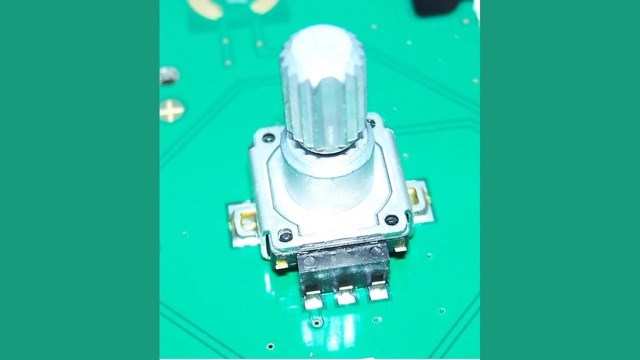
Low-cost knobs, including many EC11 and PEC11 variants, use metal contacts. As the shaft rotates, the common terminal is connected alternately to channels A and B, producing a quadrature sequence.
They are suitable for:
- menus;
- timers;
- volume controls;
- parameter adjustment;
- low-speed user interfaces.
Their advantage is simplicity. Their limitation is equally concrete: contacts bounce and wear over time.
As one specific example, the Bourns PEC11R datasheet specifies a two-bit quadrature output, a maximum contact bounce of 2 ms measured at 15 RPM, and a maximum operating speed of 60 RPM. These values belong to that component and should not be turned into universal rules for all mechanical encoders. (Bourns)
Optical encoders
An optical encoder normally uses a light source, a disk or scale, and one or more photodetectors.
Transparent and opaque regions modulate the light. Two suitably offset sensors produce signals A and B, while a separate track may generate the index.
This technology can provide high speed and high resolution. It does, however, require controlled geometry and may be affected by contamination, scale damage, or misalignment.
Magnetic encoders
A magnetic encoder measures the orientation of the field produced by a magnet attached to the shaft. The chip reconstructs the angle using Hall elements, magnetoresistive structures, or equivalent integrated sensing techniques.
The absence of physical contact and of an optical disk makes this approach attractive in the presence of:
- dust;
- condensation;
- vibration;
- tight mechanical constraints;
- a need for wear-free measurement.
This is not a geometry-free solution, however. Magnet distance, centering, tilt, and external magnetic fields all affect the result. A sensor may offer high nominal resolution and still return an inaccurate angle if it is mounted poorly.
Inductive and capacitive encoders
Inductive encoders observe changes in electromagnetic coupling between tracks or windings. Capacitive encoders instead measure capacitance variations caused by the relative movement of electrodes.
Both technologies can implement contactless sensors and provide either incremental or absolute outputs.
| Technology | Typical advantage | Limitation to consider |
|---|---|---|
| Mechanical | inexpensive and simple | bounce, wear, and limited speed |
| Optical | high resolution and speed | contamination and alignment |
| Magnetic | compact and contactless | magnet quality, centering, and external fields |
| Inductive | robust in harsh environments | more complex geometry and electronics |
| Capacitive | easy to integrate and low power | sensitivity to geometry and environment |
The table is useful for orientation, not for selecting a component. Two encoders based on the same technology may have completely different performance.
How quadrature works
An incremental quadrature encoder produces two periodic signals, A and B, nominally shifted by 90 electrical degrees, or one quarter of a cycle. (US Digital)
The second phase makes direction detection possible. With only one channel, we can tell that the shaft moved, but not whether it moved forward or backward.
One valid sequence is:
00 -> 01 -> 11 -> 10 -> 00In the opposite direction, the same sequence is traversed in reverse:
00 -> 10 -> 11 -> 01 -> 00The mapping between sequence, clockwise rotation, and counter sign depends on the wiring, the side from which the shaft is observed, and the decoder configuration. Swapping A and B normally reverses the direction.
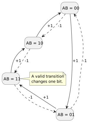
Solid arrows follow the positive cycle, while dashed arrows traverse it in reverse. Every valid transition changes one bit.
Quadrature as a cyclic code
Only one bit changes between two consecutive valid states. From 00, the next state may be 01 or 10, but not 11 directly.
A transition such as:
00 -> 11is therefore suspicious. It may indicate:
- a missed edge;
- sampling that is too slow;
- electrical noise;
- unhandled contact bounce;
- a non-atomic read of the two signals.
A robust software decoder should not interpret every change as a valid step.
A transition table
The previous state and the current state can be used as an index into a table:
| Previous state | Current state | Result |
|---|---|---|
00 |
01 |
+1 |
01 |
11 |
+1 |
11 |
10 |
+1 |
10 |
00 |
+1 |
00 |
10 |
-1 |
10 |
11 |
-1 |
11 |
01 |
-1 |
01 |
00 |
-1 |
| same state | same state | 0 |
| non-adjacent jump | any | error or 0 |
The sign can be reversed without changing the underlying principle.
This state machine is particularly useful for mechanical knobs because it separates sequence validity from the mere presence of an edge.
What happens during one complete cycle
Representing quadrature as two square waves is correct, but it can hide the behavior that actually matters to the firmware.
Suppose A is the most significant bit and B the least significant bit. During rotation in the direction we have chosen as positive, we may observe:
time t0 t1 t2 t3 t4A 0 0 1 1 0B 0 1 1 0 0state AB 00 01 11 10 00delta - +1 +1 +1 +1count 0 1 2 3 4The opposite rotation traverses the same states in reverse:
time t0 t1 t2 t3 t4A 0 1 1 0 0B 0 0 1 1 0state AB 00 10 11 01 00delta - -1 -1 -1 -1count 0 -1 -2 -3 -4With x4 decoding, every successive row represents one count. With x1 decoding, by contrast, we might update the position only when the cycle returns to 00.
This distinction explains why the same encoder can be described using apparently incompatible numbers. The physical component has not changed; the firmware policy used to interpret its edges has.
Invalid transitions and missed edges
If the firmware observes:
00 -> 11it cannot know which of the two possible paths actually occurred:
00 -> 01 -> 11or:
00 -> 10 -> 11The first path is worth +2; the second is worth -2.
The direct transition therefore contains too little information to reconstruct direction. A serious decoder should record it as an anomaly, resynchronize to the current state, and continue. Inventing a direction merely hides a missed edge.
Invalid states are precisely the transitions in which both bits change:
00 <-> 1101 <-> 10They can be detected with an XOR:
bool invalid = (previous_state ^ current_state) == 0x03;This check does not eliminate every possible error. Noise may produce a sequence made entirely of formally valid transitions. It does, however, provide a highly useful diagnostic counter: if invalid transitions increase during operation, the issue should not be ignored.
A reusable software decoder
The core logic can be separated from the method used to acquire the GPIO levels. This allows the same decoder to be used with polling, interrupts, or periodic sampling.
#include <stdbool.h>#include <stdint.h>typedef struct { int32_t count; uint32_t invalid_transitions; uint8_t previous_state;} quadrature_decoder_t;/* * Index: (previous_state << 2) | current_state * * The selected positive sequence is: * 00 -> 01 -> 11 -> 10 -> 00 */static int8_t const quadrature_transition_table[16] = { 0, +1, -1, 0, -1, 0, 0, +1, +1, 0, 0, -1, 0, -1, +1, 0,};static void quadrature_decoder_init(quadrature_decoder_t* decoder, uint8_t initial_state) { decoder->count = 0; decoder->invalid_transitions = 0; decoder->previous_state = initial_state & 0x03;}static int8_t quadrature_decoder_update(quadrature_decoder_t* decoder, uint8_t current_state) { current_state &= 0x03; uint8_t const previous_state = decoder->previous_state; if ((previous_state ^ current_state) == 0x03) { decoder->invalid_transitions++; decoder->previous_state = current_state; return 0; } uint8_t const table_index = (previous_state << 2) | current_state; int8_t const delta = quadrature_transition_table[table_index]; decoder->count += delta; decoder->previous_state = current_state; return delta;}The table contains sixteen combinations because each previous state may be followed by four possible current states.
The decoder returns:
+1for a valid transition in the positive direction;-1for a valid transition in the negative direction;0when the state does not change or the transition is invalid.
I chose to resynchronize previous_state even after an invalid jump. The firmware cannot recover the lost counts, but it avoids remaining anchored to an outdated state.
What the state machine actually filters
Consider a contact bouncing between two adjacent states:
00 -> 01 -> 00 -> 01 -> 00The decoder produces:
+1 -> -1 -> +1 -> -1The net result is zero. This is one reason why a state machine is more robust than blindly incrementing on every interrupt.
This does not mean that bounce is solved in every situation. A disturbed sequence may complete an entire valid cycle and still produce a count. Some encoders also settle with the detent at 00, others at 11, and still others at intermediate states.
For a user-interface knob, it is therefore useful to combine several layers:
- validation of A/B transitions;
- accumulation of electrical counts;
- generation of an application event only when the expected detent is reached;
- an optional time constraint or application-level filter.
The state machine understands the grammar of quadrature. It does not understand the mechanics of the component.
Full-step and half-step decoding for knobs
Libraries designed for rotary knobs often use the terms full-step and half-step to describe when a logical event is emitted.
A full-step decoder may wait for the entire cycle to complete:
00 -> 01 -> 11 -> 10 -> 00 ^ eventA half-step decoder may also emit at the opposite state:
00 -> 01 -> 11 ^ event11 -> 10 -> 00 ^ eventThis choice is related to the detent geometry, but it does not automatically correspond to x1, x2, or x4 decoding.
- x1/x2/x4 describe how many electrical edges contribute to the count;
- full-step/half-step describe when the application logic considers one step complete.
An encoder may be acquired in x4 and then converted to full-step behavior by accumulating four counts. This separation preserves all available information without forcing the UI to react to every electrical edge.
x1, x2, and x4 decoding
The same A/B pair can produce different count values depending on which edges are observed.
x1 decoding
Only one edge of one channel is counted, for example the rising edge of A.
This is the simplest approach and produces one count for every complete quadrature cycle.
If we read B when A rises, we can derive the direction:
/* Convention consistent with 00 -> 01 -> 11 -> 10. */static int8_t decode_x1_on_a_rising(void) { return gpio_get_level(ENCODER_GPIO_B) ? +1 : -1;}By connecting only A, we can still count pulses and estimate a frequency, but we lose direction information. A single channel is therefore sufficient for a unidirectional tachometer, not for a position that may move both forward and backward.
x2 decoding
Both edges of one channel are counted:
- rising edge of A;
- falling edge of A.
The resolution doubles compared with x1.
With the convention used in this article, after every edge of A the positive direction corresponds to A == B:
static int8_t decode_x2_on_any_a_edge(void) { int const a = gpio_get_level(ENCODER_GPIO_A); int const b = gpio_get_level(ENCODER_GPIO_B); return a == b ? +1 : -1;}This rule is compact, but it does not validate the complete sequence. If an edge on B is missed, the firmware may still update the count without noticing the anomaly.
x4 decoding
Both edges of both channels are counted:
- rising edge of A;
- falling edge of A;
- rising edge of B;
- falling edge of B.
The theoretical resolution becomes four times that obtained by observing one edge per cycle.
PCNT can implement this decoding with two cross-coupled channels: A is used as the edge signal and B as the direction-control signal; on the second channel, the roles are reversed. This is the same architecture used by Espressif's official rotary_encoder example. (Espressif: PCNT example)
PPR, CPR, pulses, and positions
Commercial terminology is one of the easiest parts of the subject to misinterpret.
Depending on the manufacturer:
CPRmay mean cycles per revolution;PPRmay refer to pulses before or after quadrature multiplication;- positions per revolution may refer to x4 states;
- steps per revolution may refer to mechanical detents;
- detents may not coincide with one complete electrical cycle.
It is therefore not enough to read “600 PPR” and automatically multiply it by four.
The datasheet must be checked for:
- how many cycles each channel produces;
- whether the declared value already includes x4 decoding;
- how many edges the firmware will count;
- whether a gearbox or mechanical ratio is present;
- how many electrical states correspond to one detent.
For convenience, throughout the rest of the article I will use the expression counts per revolution to mean the value actually observed by the software after the selected decoding method.
Converting counts to angle
Once the effective counts per revolution are known, the angle within one revolution can be calculated as:
angle = count_within_revolution * 360 / counts_per_revolutionWith 4096 counts per revolution:
nominal_resolution = 360 / 4096 = 0.087890625 degrees per countTo preserve a multi-turn position, it is better to keep the extended counter and calculate separately:
complete_revolutions = count / counts_per_revolutionangle_within_revolution = count mod counts_per_revolutionIn C, negative values require attention. The % operator returns a remainder, which is not always the positive mathematical modulo we expect.
A useful helper is:
static int positive_modulo(int value, int modulo) { int result = value % modulo; return result < 0 ? result + modulo : result;}Resolution, accuracy, and repeatability
These terms are often used as synonyms. They are not.
Resolution
Resolution is the smallest increment that the output can represent.
A system with 4096 counts per revolution can nominally distinguish steps of about 0.088 degrees. This does not mean that it knows the real angle with a maximum error of 0.088 degrees.
Accuracy
Accuracy describes how close the indicated position is to the true position.
It may be limited by:
- eccentricity;
- sensor nonlinearity;
- scale error;
- misalignment;
- an off-center magnet;
- mechanical play;
- temperature;
- structural deformation;
- interpolation error.
Repeatability
Repeatability describes the ability to return the same value when the axis returns to the same position.
A system may be highly repeatable but inaccurate: it returns to the same value every time, but that value is offset from the true position.
Renishaw explicitly distinguishes the three quantities: resolution is the smallest output step, accuracy measures closeness to the true value, and repeatability indicates the ability to report the same position on successive returns. (Renishaw: FAQ)
Sensor resolution is not axis resolution
Between the encoder and the load there may be:
- couplings;
- belts;
- pulleys;
- gearboxes;
- gears;
- structural flex;
- backlash;
- vibration.
The design should therefore not begin with the question, “How many bits does the sensor have?” A more concrete question is:
What is the maximum error I can accept on the mechanical part that actually matters?
Encoder electrical outputs
Two encoders producing the same quadrature signals may require completely different interface circuits.
Contacts connected to a common terminal
Mechanical knobs often have three terminals:
AC, commonBThe common terminal is connected to ground, while A and B are held high through pull-up resistors. When a contact closes, the corresponding line is pulled low.
The ESP32's internal pull-ups are convenient for prototypes. In a product, external resistors provide better control over:
- contact current;
- line impedance;
- rise time;
- noise immunity;
- interaction with any capacitors.
Values such as 4.7 kΩ or 10 kΩ are common starting points, not a rule. The correct value depends on the circuit and the maximum frequency.
Push-pull output
A push-pull output actively drives both the high and low levels.
Its edges are generally faster than those of an open-collector output with a weak pull-up, but its output voltage must be compatible with the microcontroller GPIO.
Open-collector output
An open-collector output actively pulls the line toward ground and requires an external pull-up to obtain a high level.
In some cases, the pull-up may be connected to 3.3 V even when the encoder itself is powered from a higher voltage. This must, however, be confirmed by the datasheet: maximum voltages, currents, leakage, and internal circuitry all need to be checked.
Differential line driver
Industrial encoders may provide complementary pairs:
A /AB /BZ /ZThe receiver measures the difference between the two conductors. Noise coupled similarly onto both wires is therefore largely rejected.
Line-driver outputs are suitable for long cables and high frequencies, but they require an appropriate receiver, often one compatible with RS-422. Omron, for example, describes its line-driver outputs as RS-422A compatible and intended for transmission over twisted pairs. (Omron)
Connecting A and /A to two GPIOs and subtracting their levels in software is not equivalent.
5 V, 12 V, and 24 V levels
Many industrial encoders operate at voltages higher than 3.3 V.
ESP GPIOs must not be treated as 5 V-tolerant inputs. Espressif's hardware FAQ states a GPIO tolerance of 3.6 V and recommends level adaptation when this value is exceeded. (Espressif: GPIO)
Depending on the interface, the circuit may require:
- a resistor divider;
- a transistor;
- a Schmitt-trigger buffer;
- a comparator;
- a level shifter;
- an RS-422 receiver;
- an optocoupler;
- a digital isolator.
The choice depends on frequency, cable length, common-ground conditions, voltage, and isolation requirements.
Bounce, noise, and filtering
Mechanical bounce and electrical noise are not the same problem.
Mechanical bounce
When a contact closes, the transition is not instantaneous. The signal may oscillate before settling:
0 -> 1 -> 0 -> 1 -> 0 -> 1A decoder that counts every edge interprets this sequence as several movements.
Electrical noise
Noise may be generated by:
- motors;
- PWM;
- relays;
- switching power supplies;
- long cables;
- poorly shared grounds;
- electrostatic discharges;
- capacitive or inductive coupling;
- Wi-Fi and Bluetooth radios in a poorly designed layout.
It can produce short pulses or move the signal around the logic threshold.
RC filtering
An RC filter attenuates rapid changes, but it also slows the edges.
If the time constant is too large:
- the maximum frequency is reduced;
- the timing relationship between A and B is altered;
- valid transitions are lost;
- the input crosses the threshold slowly;
- rapid reversals become ambiguous.
A larger capacitor does not automatically produce a better signal.
The filter must be sized from the minimum valid pulse width and verified on the real circuit. When edges become slow, adding a Schmitt-trigger buffer may be appropriate.
Time-based software debounce
A simple approach is to ignore every transition received within a fixed interval.
This may work for a slow knob, but it cannot distinguish bounce from genuine fast movement. A window that is too long removes valid steps; one that is too short lets bounce through.
State-based decoding
For mechanical encoders, validating the entire A/B sequence is often preferable.
The firmware can accumulate allowed transitions and generate an application event only after a cycle is completed or the expected detent is reached.
This separates three concepts that are frequently confused:
- electrical edge;
- quadrature count;
- step perceived by the user.
Reading an encoder with ESP-IDF
There is no single correct way to read an encoder. The choice depends on edge frequency, required accuracy, available peripherals, and the information we want to obtain.
| Method | Primary information | Advantage | Limitation |
|---|---|---|---|
| Polling in a task | position and direction | simple to observe and debug | jitter and missed edges |
| GPIO interrupts | position and direction | no work while the signal is idle | ISR load and possible state jumps |
| GPTimer + state machine | position and direction | deterministic periodic sampling | continuous interrupts even while idle |
| PCNT | position and direction | hardware x4 counting | not available on every target |
| MCPWM Capture | period and speed | hardware edge timestamps | not a complete position decoder |
| SPI, SSI, or BiSS | absolute position | angle available at startup | protocol overhead and serial sampling |
| Absolute PWM | position within one revolution | only one signal | duty-cycle measurement and latency |
| RS-422 receiver + PCNT | industrial quadrature | robust over long cables | additional hardware |
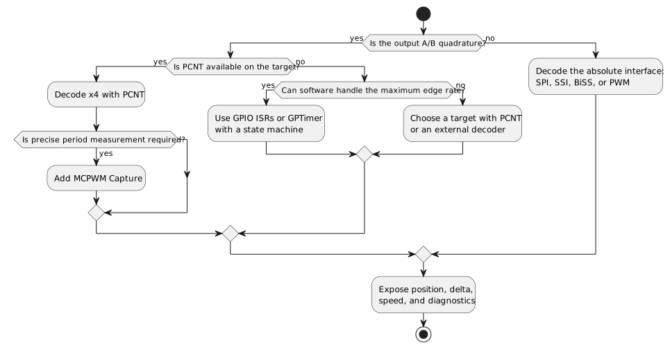
Choose the peripheral from the available signal, maximum frequency, and required information, not from API convenience.
Before writing code, it is useful to calculate the maximum event frequency.
If counts_per_revolution represents the effective count after the chosen multiplication, the count frequency is:
f_count = counts_per_revolution * RPM / 60An encoder with 600 periods per revolution read in x4 produces 2400 counts per revolution. At 3000 RPM:
f_count = 2400 * 3000 / 60 = 120000 counts per secondOne hundred and twenty thousand events per second make a task that reads the GPIOs every millisecond clearly unsuitable. A user-interface knob, by contrast, may operate several orders of magnitude more slowly.
Reading both GPIO states
The software examples use a common helper:
#include "driver/gpio.h"#define ENCODER_GPIO_A GPIO_NUM_18#define ENCODER_GPIO_B GPIO_NUM_19static inline uint8_t encoder_read_gpio_state(void) { uint8_t const a = (uint8_t)gpio_get_level(ENCODER_GPIO_A); uint8_t const b = (uint8_t)gpio_get_level(ENCODER_GPIO_B); return (uint8_t)((a << 1) | b);}The two calls to gpio_get_level() do not necessarily form an atomic snapshot of the pins. If A changes between the first and second read, the firmware may construct a state that never existed as a stable pair.
For a slow mechanical encoder, the risk is often acceptable. At high speed or under tighter requirements, this is another reason to prefer a hardware peripheral such as PCNT.
Common GPIO configuration
For a mechanical encoder whose common terminal is connected to ground, we can start with:
static esp_err_t encoder_gpio_init(gpio_int_type_t interrupt_type) { gpio_config_t const config = { .pin_bit_mask = (1ULL << ENCODER_GPIO_A) | (1ULL << ENCODER_GPIO_B), .mode = GPIO_MODE_INPUT, .pull_up_en = GPIO_PULLUP_ENABLE, .pull_down_en = GPIO_PULLDOWN_DISABLE, .intr_type = interrupt_type, }; return gpio_config(&config);}The internal pull-ups are convenient during bring-up. In a product, external resistors provide better control over current, impedance, and noise immunity.
Method 1: Polling from a task
Polling is the easiest method to understand. A task samples A and B, updates the decoder, and forwards increments to the application logic.
#include "freertos/FreeRTOS.h"#include "freertos/task.h"#define ENCODER_POLL_PERIOD_MS 1static quadrature_decoder_t polling_decoder;static void encoder_polling_task(void* argument) { (void)argument; quadrature_decoder_init(&polling_decoder, encoder_read_gpio_state()); TickType_t last_wake_time = xTaskGetTickCount(); while (true) { uint8_t const state = encoder_read_gpio_state(); int8_t const delta = quadrature_decoder_update(&polling_decoder, state); if (delta != 0) { process_encoder_delta(delta); } xTaskDelayUntil(&last_wake_time, pdMS_TO_TICKS(ENCODER_POLL_PERIOD_MS)); }}Initialization can be reduced to:
ESP_ERROR_CHECK(encoder_gpio_init(GPIO_INTR_DISABLE));BaseType_t task_created = xTaskCreate(encoder_polling_task, "encoder_poll", 3072, NULL, 5, NULL);if (task_created != pdPASS) { ESP_LOGE("encoder", "Unable to create polling task");}A 1 ms period nominally corresponds to 1 kHz. That does not mean we can reliably read a 1 kHz signal.
To observe every state, we need several samples per transition and must account for:
- scheduler jitter;
- critical sections;
- higher-priority tasks;
- Flash operations;
- Wi-Fi and Bluetooth activity;
- the execution time of the code inside the task.
I would use polling only when the maximum edge frequency is far below the sampling frequency and an occasional missed step is acceptable.
Method 2: GPIO interrupts on both channels
Interrupts eliminate continuous sampling. The firmware runs only when A or B changes.
ESP-IDF allows a global ISR service to be installed and separate handlers to be associated with individual GPIOs through gpio_isr_handler_add(). The callback still runs in interrupt context and has a smaller stack than a task. (Espressif: GPIO)
A minimal implementation can update the decoder in the ISR and notify a task:
#include "freertos/FreeRTOS.h"#include "freertos/task.h"static portMUX_TYPE encoder_isr_lock = portMUX_INITIALIZER_UNLOCKED;static quadrature_decoder_t interrupt_decoder;static TaskHandle_t encoder_consumer_task_handle;static void encoder_gpio_isr(void* argument) { (void)argument; uint8_t const state = encoder_read_gpio_state(); portENTER_CRITICAL_ISR(&encoder_isr_lock); int8_t const delta = quadrature_decoder_update(&interrupt_decoder, state); portEXIT_CRITICAL_ISR(&encoder_isr_lock); if (delta != 0 && encoder_consumer_task_handle != NULL) { BaseType_t task_woken = pdFALSE; vTaskNotifyGiveFromISR(encoder_consumer_task_handle, &task_woken); if (task_woken == pdTRUE) { portYIELD_FROM_ISR(); } }}The task must not assume that each notification corresponds to a single count. Notifications may accumulate or merge. It is better to read a snapshot of the counter:
static void encoder_interrupt_consumer_task(void* argument) { (void)argument; int32_t previous_count = 0; while (true) { ulTaskNotifyTake(pdTRUE, portMAX_DELAY); int32_t current_count; uint32_t invalid_transitions; portENTER_CRITICAL(&encoder_isr_lock); current_count = interrupt_decoder.count; invalid_transitions = interrupt_decoder.invalid_transitions; portEXIT_CRITICAL(&encoder_isr_lock); int32_t const delta = current_count - previous_count; previous_count = current_count; if (delta != 0) { process_encoder_delta(delta); } if (invalid_transitions != 0) { ESP_LOGW("encoder", "Invalid transitions: %" PRIu32, invalid_transitions); } }}Initialization:
static esp_err_t encoder_gpio_interrupt_init(void) { ESP_RETURN_ON_ERROR(encoder_gpio_init(GPIO_INTR_ANYEDGE), "encoder", "Unable to configure GPIOs"); quadrature_decoder_init(&interrupt_decoder, encoder_read_gpio_state()); esp_err_t ret = gpio_install_isr_service(0); if (ret != ESP_OK && ret != ESP_ERR_INVALID_STATE) { return ret; } ESP_RETURN_ON_ERROR( gpio_isr_handler_add(ENCODER_GPIO_A, encoder_gpio_isr, NULL), "encoder", "Unable to register ISR for A" ); ESP_RETURN_ON_ERROR( gpio_isr_handler_add(ENCODER_GPIO_B, encoder_gpio_isr, NULL), "encoder", "Unable to register ISR for B" ); return ESP_OK;}The complete source also needs:
#include <inttypes.h>#include "esp_check.h"#include "esp_log.h"The consumer task must be created before the handlers are enabled so that the ISR already has a valid destination:
BaseType_t task_created = xTaskCreate( encoder_interrupt_consumer_task, "encoder_consumer", 4096, NULL, 6, &encoder_consumer_task_handle);if (task_created != pdPASS) { ESP_LOGE("encoder", "Unable to create consumer task"); return ESP_ERR_NO_MEM;}ESP_ERROR_CHECK(encoder_gpio_interrupt_init());This approach works well at moderate frequencies, but it has an important limitation. If two edges arrive before the ISR can read the intermediate state, the decoder may observe an invalid jump.
In other words, the interrupt tells us that something changed; it does not guarantee that the firmware can reconstruct every phase as the frequency increases.
Method 3: GPTimer and periodic sampling
A GPTimer can generate a periodic alarm and sample the GPIOs at a more deterministic cadence than a normal task.
The timer callback runs in ISR context. It must therefore remain short and cannot contain blocking operations. ESP-IDF allows the alarm to auto-reload, producing a periodic event. (Espressif: GPTimer)
The following example samples at 1 kHz:
#include "driver/gptimer.h"#define ENCODER_SAMPLE_TIMER_HZ 1000000#define ENCODER_SAMPLE_PERIOD_US 1000static gptimer_handle_t encoder_sample_timer;static portMUX_TYPE encoder_timer_lock = portMUX_INITIALIZER_UNLOCKED;static quadrature_decoder_t timer_decoder;static bool encoder_sample_timer_callback( gptimer_handle_t timer, gptimer_alarm_event_data_t const* event_data, void* user_context) { (void)timer; (void)event_data; (void)user_context; uint8_t const state = encoder_read_gpio_state(); portENTER_CRITICAL_ISR(&encoder_timer_lock); quadrature_decoder_update(&timer_decoder, state); portEXIT_CRITICAL_ISR(&encoder_timer_lock); return false;}static esp_err_t encoder_sample_timer_init(void) { quadrature_decoder_init(&timer_decoder, encoder_read_gpio_state()); gptimer_config_t const timer_config = { .clk_src = GPTIMER_CLK_SRC_DEFAULT, .direction = GPTIMER_COUNT_UP, .resolution_hz = ENCODER_SAMPLE_TIMER_HZ, }; ESP_RETURN_ON_ERROR( gptimer_new_timer(&timer_config, &encoder_sample_timer), "encoder", "Unable to create GPTimer" ); gptimer_event_callbacks_t const callbacks = { .on_alarm = encoder_sample_timer_callback, }; ESP_RETURN_ON_ERROR( gptimer_register_event_callbacks(encoder_sample_timer, &callbacks, NULL), "encoder", "Unable to register GPTimer callback" ); gptimer_alarm_config_t const alarm_config = { .reload_count = 0, .alarm_count = ENCODER_SAMPLE_PERIOD_US, .flags.auto_reload_on_alarm = true, }; ESP_RETURN_ON_ERROR( gptimer_set_alarm_action(encoder_sample_timer, &alarm_config), "encoder", "Unable to configure alarm" ); ESP_RETURN_ON_ERROR(gptimer_enable(encoder_sample_timer), "encoder", "Unable to enable GPTimer"); return gptimer_start(encoder_sample_timer);}The CMakeLists.txt must include:
PRIV_REQUIRES esp_driver_gptimer esp_driver_gpioA task can periodically read a snapshot of the decoder without running application logic inside the callback:
static void encoder_timer_consumer_task(void* argument) { (void)argument; int32_t previous_count = 0; while (true) { int32_t current_count; portENTER_CRITICAL(&encoder_timer_lock); current_count = timer_decoder.count; portEXIT_CRITICAL(&encoder_timer_lock); int32_t const delta = current_count - previous_count; previous_count = current_count; if (delta != 0) { process_encoder_delta(delta); } vTaskDelay(pdMS_TO_TICKS(10)); }}A complete startup sequence can be organized as follows:
ESP_ERROR_CHECK(encoder_gpio_init(GPIO_INTR_DISABLE));BaseType_t task_created = xTaskCreate(encoder_timer_consumer_task, "encoder_timer_consumer", 3072, NULL, 5, NULL);if (task_created != pdPASS) { ESP_LOGE("encoder", "Unable to create GPTimer task"); return ESP_ERR_NO_MEM;}ESP_ERROR_CHECK(encoder_sample_timer_init());This solution is interesting for a slow, bouncing knob because it gives the state machine a constant sampling rhythm. It does, however, generate interrupts even while the encoder is idle.
At 1 kHz, that means one thousand callbacks per second that do nothing most of the time. The cost may be acceptable in a simple device, but it should be measured when the firmware also contains radios, audio, displays, or control loops.
Method 4: PCNT as a hardware decoder
PCNT stands for Pulse Counter.
The peripheral counts edges in hardware and can use a second signal to control the counting direction. By combining an edge input and a level input, one PCNT unit can act as a quadrature decoder. (Espressif: PCNT)
The advantage is not merely a lower interrupt count. Counting continues while the CPU executes other tasks, provided that the peripheral and its clock domain remain operational.
PCNT also provides:
- a hardware filter for short glitches;
- counter limits;
- a software accumulator for extending the count;
- watch points;
- fixed-step notifications;
- ISR callbacks;
- periodic reads without handling every edge in software.
PCNT does not, however, provide a counter of semantically invalid A/B transitions. It configures actions based on edges and levels, but it does not reconstruct a complete software history of the states. A logic analyzer remains useful for diagnosing wiring and noise.
Method 5: MCPWM Capture for period measurement
MCPWM Capture does not replace PCNT for position measurement. Its strength is recording an edge timestamp in hardware.
It is therefore useful when estimating low-frequency speed from the period between two pulses. The peripheral exposes both the captured value and the edge type in the callback, while the timer resolution allows ticks to be converted into seconds. (Espressif: MCPWM)
We will examine a complete example in the section dedicated to speed calculation.
Method 6: Absolute interfaces and encoded signals
A serial absolute encoder must not be treated as quadrature.
Depending on the device, we may need to read:
- an SPI word with parity and error bits;
- an SSI or BiSS frame synchronized by a clock;
- a PWM duty cycle proportional to angle;
- an analog sine/cosine pair;
- a proprietary industrial protocol.
The logic is different:
quadrature -> reconstruct motion from edgesabsolute -> sample an already encoded positionThe firmware must follow the sensor datasheet. There is no generic read_absolute_encoder() function that can replace the frame format, timing, diagnostics, and error handling required by a specific device.
PCNT is not available on every ESP32
The ESP32 family is not a single microcontroller. Its peripherals vary from one target to another.
The knob component documentation lists hardware PCNT support on ESP32, ESP32-S2, ESP32-S3, ESP32-C6, and ESP32-H2, while ESP32-C2 and ESP32-C3 use software decoding. (Espressif: Knob)
This list should not be treated as permanent or exhaustive. Newer families may add other targets. Before designing the architecture, it is worth checking:
- the target's Peripherals API page;
- the SoC datasheet;
- the Supported Targets table for the PCNT example in the ESP-IDF version being used.
If the target documentation does not contain a PCNT section, including driver/pulse_cnt.h will not make the peripheral appear by magic.
The current PCNT driver
Starting with ESP-IDF 6.0, the legacy driver/pcnt.h header was removed. The current driver lives in the esp_driver_pcnt component and uses the driver/pulse_cnt.h header. (Espressif: 6.0 migration guide)
Its main objects are:
pcnt_unit_handle_t;pcnt_channel_handle_t.
The unit contains the counter. Channels define how the inputs modify that counter.
For each channel, we can configure:
- the edge-signal GPIO;
- the level-signal GPIO;
- the action on a rising edge;
- the action on a falling edge;
- behavior when the control signal is high;
- behavior when the control signal is low;
- optional input inversion.
The logic can be summarized as follows:
increment on a rising edgedecrement on a falling edgewhen the second signal changes level, keep or reverse the directionWith two cross-coupled channels, both A and B contribute to x4 decoding.
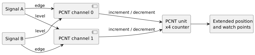
Each signal drives the edges of one channel and controls the direction of the other. Both actions feed the same PCNT unit.
Configuring PCNT for a quadrature encoder
We can now move to the code.
The following example targets the handle-based APIs in ESP-IDF 6.0.x. It configures two cross-coupled channels, enables an extended count beyond the hardware register limits, and applies a filter for very short glitches.
One point deserves to be stated clearly: the filter value and GPIO numbers are examples only. They should not be copied without checking the real signal and the characteristics of the selected target.
#include <stddef.h>#include "driver/gpio.h"#include "driver/pulse_cnt.h"#include "esp_check.h"#include "esp_err.h"#include "esp_log.h"#define ENCODER_GPIO_A GPIO_NUM_18#define ENCODER_GPIO_B GPIO_NUM_19#define ENCODER_PCNT_LOW_LIMIT -30000#define ENCODER_PCNT_HIGH_LIMIT 30000static char const* TAG = "encoder";static pcnt_unit_handle_t encoder_unit;static pcnt_channel_handle_t encoder_channel_a;static pcnt_channel_handle_t encoder_channel_b;esp_err_t encoder_init(void) { esp_err_t ret; pcnt_unit_config_t unit_config = { .low_limit = ENCODER_PCNT_LOW_LIMIT, .high_limit = ENCODER_PCNT_HIGH_LIMIT, .flags.accum_count = true, }; ESP_RETURN_ON_ERROR( pcnt_new_unit(&unit_config, &encoder_unit), TAG, "Unable to create PCNT unit" ); /* * The filter removes only pulses shorter than the threshold. * It does not replace debounce for a mechanical encoder. */ pcnt_glitch_filter_config_t const filter_config = { .max_glitch_ns = 1000, }; ESP_GOTO_ON_ERROR( pcnt_unit_set_glitch_filter(encoder_unit, &filter_config), error_delete_unit, TAG, "Unable to configure PCNT filter" ); /* * This configuration assumes contacts connected to ground. * External pull-ups are often preferable in a real product. */ ESP_GOTO_ON_ERROR( gpio_pullup_en(ENCODER_GPIO_A), error_delete_unit, TAG, "Unable to enable pull-up on channel A" ); ESP_GOTO_ON_ERROR( gpio_pullup_en(ENCODER_GPIO_B), error_delete_unit, TAG, "Unable to enable pull-up on channel B" ); pcnt_chan_config_t const channel_a_config = { .edge_gpio_num = ENCODER_GPIO_A, .level_gpio_num = ENCODER_GPIO_B, }; ESP_GOTO_ON_ERROR( pcnt_new_channel(encoder_unit, &channel_a_config, &encoder_channel_a), error_delete_unit, TAG, "Unable to create channel A" ); pcnt_chan_config_t const channel_b_config = { .edge_gpio_num = ENCODER_GPIO_B, .level_gpio_num = ENCODER_GPIO_A, }; ESP_GOTO_ON_ERROR( pcnt_new_channel(encoder_unit, &channel_b_config, &encoder_channel_b), error_delete_channel_a, TAG, "Unable to create channel B" ); /* * These actions follow the decoder used by Espressif's * official rotary_encoder example. */ ESP_GOTO_ON_ERROR( pcnt_channel_set_edge_action( encoder_channel_a, PCNT_CHANNEL_EDGE_ACTION_DECREASE, PCNT_CHANNEL_EDGE_ACTION_INCREASE ), error_delete_channels, TAG, "Unable to configure channel A edge actions" ); ESP_GOTO_ON_ERROR( pcnt_channel_set_level_action( encoder_channel_a, PCNT_CHANNEL_LEVEL_ACTION_KEEP, PCNT_CHANNEL_LEVEL_ACTION_INVERSE ), error_delete_channels, TAG, "Unable to configure channel A level action" ); ESP_GOTO_ON_ERROR( pcnt_channel_set_edge_action( encoder_channel_b, PCNT_CHANNEL_EDGE_ACTION_INCREASE, PCNT_CHANNEL_EDGE_ACTION_DECREASE ), error_delete_channels, TAG, "Unable to configure channel B edge actions" ); ESP_GOTO_ON_ERROR( pcnt_channel_set_level_action( encoder_channel_b, PCNT_CHANNEL_LEVEL_ACTION_KEEP, PCNT_CHANNEL_LEVEL_ACTION_INVERSE ), error_delete_channels, TAG, "Unable to configure channel B level action" ); /* * With accum_count enabled, both limits must be added as watch * points so the driver can compensate for hardware overflows. */ ESP_GOTO_ON_ERROR( pcnt_unit_add_watch_point(encoder_unit, ENCODER_PCNT_LOW_LIMIT), error_delete_channels, TAG, "Unable to add lower limit" ); ESP_GOTO_ON_ERROR( pcnt_unit_add_watch_point(encoder_unit, ENCODER_PCNT_HIGH_LIMIT), error_remove_low_watch_point, TAG, "Unable to add upper limit" ); ESP_GOTO_ON_ERROR( pcnt_unit_enable(encoder_unit), error_remove_watch_points, TAG, "Unable to enable PCNT" ); /* * Clearing applies the newly added watch points and resets both * the hardware counter and the software accumulator. */ ESP_GOTO_ON_ERROR( pcnt_unit_clear_count(encoder_unit), error_disable_unit, TAG, "Unable to clear PCNT" ); ESP_GOTO_ON_ERROR(pcnt_unit_start(encoder_unit), error_disable_unit, TAG, "Unable to start PCNT"); return ESP_OK;error_disable_unit: pcnt_unit_disable(encoder_unit);error_remove_watch_points: pcnt_unit_remove_watch_point(encoder_unit, ENCODER_PCNT_HIGH_LIMIT);error_remove_low_watch_point: pcnt_unit_remove_watch_point(encoder_unit, ENCODER_PCNT_LOW_LIMIT);error_delete_channels: pcnt_del_channel(encoder_channel_b); encoder_channel_b = NULL;error_delete_channel_a: pcnt_del_channel(encoder_channel_a); encoder_channel_a = NULL;error_delete_unit: pcnt_del_unit(encoder_unit); encoder_unit = NULL; return ret;}esp_err_t encoder_get_count(int* count) { if (count == NULL || encoder_unit == NULL) { return ESP_ERR_INVALID_ARG; } return pcnt_unit_get_count(encoder_unit, count);}esp_err_t encoder_reset(void) { if (encoder_unit == NULL) { return ESP_ERR_INVALID_STATE; } return pcnt_unit_clear_count(encoder_unit);}esp_err_t encoder_deinit(void) { if (encoder_unit == NULL) { return ESP_OK; } ESP_RETURN_ON_ERROR(pcnt_unit_stop(encoder_unit), TAG, "Unable to stop PCNT"); ESP_RETURN_ON_ERROR(pcnt_unit_disable(encoder_unit), TAG, "Unable to disable PCNT"); ESP_RETURN_ON_ERROR(pcnt_del_channel(encoder_channel_b), TAG, "Unable to delete channel B"); ESP_RETURN_ON_ERROR(pcnt_del_channel(encoder_channel_a), TAG, "Unable to delete channel A"); ESP_RETURN_ON_ERROR(pcnt_del_unit(encoder_unit), TAG, "Unable to delete PCNT unit"); encoder_channel_b = NULL; encoder_channel_a = NULL; encoder_unit = NULL; return ESP_OK;}The action configuration follows the official rotary_encoder example. In particular, one channel uses A as the edge input and B as the control input, while the other does the opposite. (Espressif: PCNT example)
The resulting direction may not match the direction expected by the application. This is not necessarily an error.
We can:
- swap A and B;
- invert the sign at application level;
- use the input-inversion flags;
- modify the actions associated with the edges.
I prefer to keep the driver consistent with the wiring and convert the sign only once, at the layer that assigns application meaning to the movement.
The component's CMakeLists.txt must declare the correct dependencies:
idf_component_register( SRCS "encoder.c" INCLUDE_DIRS "." PRIV_REQUIRES esp_driver_pcnt esp_driver_gpio)The current documentation associates the driver with the driver/pulse_cnt.h header and the esp_driver_pcnt component. (Espressif: PCNT)
A note on error handling
The previous code includes a cleanup path because peripheral resources can be exhausted and every call can fail.
For a teaching example, using ESP_ERROR_CHECK() would have been shorter. Inside a reusable component, however, restarting the entire firmware because one resource is unavailable is not always the desired behavior.
The choice depends on the project:
- during bring-up,
ESP_ERROR_CHECK()makes the problem immediately visible; - in a product, returning the error and letting the upper layer decide may be preferable;
- if the encoder is safety-critical, an initialization error must put the system into a known state.
Counter limits and extended position
The PCNT hardware register is not infinite.
On ESP32, the hardware counter is a signed 16-bit value. In addition, the configured high and low limits are not merely informational thresholds: when either is reached, the hardware counter resets to zero. (Espressif: PCNT)
If we read only the hardware register, an increasing position could therefore behave as follows:
299982999930000012For a knob that controls a value between 0 and 100, this may not matter. For a multi-turn axis, however, the jump would make the position unusable.
The flag:
.flags.accum_count = trueasks the driver to compensate for overflows in software. The configuration is not complete, however, until both the high and low limits have been added as watch points. (Espressif: PCNT)
The correct sequence is therefore:
- configure sufficiently wide limits;
- enable
accum_count; - add both limits as watch points;
- enable the unit;
- call
pcnt_unit_clear_count(); - start counting.
At that point, pcnt_unit_get_count() returns the sum of the hardware counter and the software accumulator.
Keep in mind that each overflow still requires internal event handling. Limits that are too narrow unnecessarily increase interrupt frequency. Espressif recommends making them wide enough to reduce the risk of multiple overflows occurring before they can be processed. (Espressif: PCNT)
Finally, pcnt_unit_clear_count() clears both the hardware portion and the accumulator. It should therefore not be used as a simple synchronization operation when the extended position must be preserved.
The glitch filter is not debounce
The PCNT filter ignores pulses shorter than the value specified by max_glitch_ns:
pulse width < max_glitch_ns -> pulse ignoredpulse width >= max_glitch_ns -> pulse can be observedThis mechanism is useful against very short electrical disturbances. It does not understand quadrature and knows nothing about the encoder mechanics.
A 500 µs contact bounce is enormously longer than a filter configured for 1000 ns. From the peripheral's perspective, it is therefore a perfectly valid edge.
The right question is not:
How high can I set the filter until the bounce disappears?
It is instead:
What is the shortest valid pulse at the maximum expected speed, and what margin can I leave relative to the real glitches?
Suppose the signal reaches a maximum frequency f and has a duty cycle close to 50%. The period is:
T = 1 / fThe nominal duration of each half-cycle is approximately:
T_high ≈ T_low ≈ T / 2The filter threshold must remain comfortably below the shortest half-cycle. Otherwise it will begin deleting real information.
The filter uses the APB clock. When Dynamic Frequency Scaling is enabled, the driver acquires a power-management lock while the unit is enabled so that the required timing remains stable. (Espressif: PCNT)
This detail is easy to overlook, but it affects power consumption. A seemingly harmless filter can prevent the APB clock from dropping to its minimum frequency while PCNT is active.
Watch points and callbacks
Watch points generate an event when the count reaches a specific value.
They can be useful for:
- notifying a zero crossing;
- detecting a software limit;
- updating a task every certain number of counts;
- compensating for overflows;
- detecting a position of interest.
Resources are limited, so creating one watch point for every possible position is not sensible.
After adding a new watch point, the documentation requires a call to pcnt_unit_clear_count() for the configuration to become immediately effective. (Espressif: PCNT)
The on_reach callback runs in ISR context. This means it must not:
- block;
- allocate memory;
- perform heavy logging;
- access slow peripherals;
- call FreeRTOS APIs that do not have the
FromISRsuffix.
A minimal callback can send the value to a queue:
#include "freertos/FreeRTOS.h"#include "freertos/queue.h"static bool encoder_on_reach( pcnt_unit_handle_t unit, pcnt_watch_event_data_t const* event, void* user_context) { (void)unit; QueueHandle_t queue = (QueueHandle_t)user_context; BaseType_t higher_priority_task_woken = pdFALSE; xQueueSendFromISR(queue, &event->watch_point_value, &higher_priority_task_woken); return higher_priority_task_woken == pdTRUE;}The callback is registered before enabling the unit:
pcnt_event_callbacks_t callbacks = { .on_reach = encoder_on_reach,};ESP_ERROR_CHECK(pcnt_unit_register_event_callbacks(encoder_unit, &callbacks, event_queue));The callback should not contain the user-interface or motor-control logic. Its job is to transfer information into a context where normal timing and APIs are available.
For a user-interface knob, no callback is needed in most cases. We can let PCNT accumulate edges and read the position periodically:
int previous_count = 0;while (true) { int current_count; ESP_ERROR_CHECK(encoder_get_count(¤t_count)); int const delta = current_count - previous_count; previous_count = current_count; if (delta != 0) { process_encoder_delta(delta); } vTaskDelay(pdMS_TO_TICKS(10));}The task does not need to be scheduled on every edge. That is precisely one of the main advantages of hardware counting.
Watch step: notifications every N counts
ESP-IDF 6.0.2 also exposes pcnt_unit_add_watch_step(). Unlike a static watch point, a step notification is generated when the accumulated increment reaches a positive or negative interval. (Espressif: PCNT)
For a knob that produces four counts per detent, we can request events in both directions:
#define COUNTS_PER_DETENT 4ESP_ERROR_CHECK(pcnt_unit_add_watch_step(encoder_unit, +COUNTS_PER_DETENT));ESP_ERROR_CHECK(pcnt_unit_add_watch_step(encoder_unit, -COUNTS_PER_DETENT));The same on_reach callback is used for both watch points and step notifications. The watch_point_value field contains the counter value at the time of the event.
This mechanism avoids creating a long list of absolute thresholds. It does not, however, automatically turn four edges into one reliable mechanical detent.
If bounce produces four net counts, the notification will still be generated. The peripheral sees pulses and direction; it does not know the mechanical meaning of the detent.
I would use watch step when a task must be woken every N counts without continuously polling the counter. For a simple UI, periodic reads are often easier to control and debug.
From electrical counts to knob detents
A mechanical knob may produce four x4 counts for every detent perceived by the user.
In that case, updating the UI on every count would move the value by four units per detent.
We can accumulate the delta and generate an event only after the expected number of transitions has been completed:
#define COUNTS_PER_DETENT 4static int residual_count;void process_encoder_delta(int delta) { residual_count += delta; while (residual_count >= COUNTS_PER_DETENT) { residual_count -= COUNTS_PER_DETENT; ui_encoder_step(+1); } while (residual_count <= -COUNTS_PER_DETENT) { residual_count += COUNTS_PER_DETENT; ui_encoder_step(-1); }}The value 4 is not universal.
Some encoders complete one electrical cycle per detent. Others settle in an intermediate state. On some models, the declared pulse count does not match the number of mechanical detents.
The solution?
Turn the encoder slowly, observe A and B, and measure:
- the stable state at each detent;
- the number of edges between two detents;
- behavior during reversals;
- the count produced by one complete revolution.
Only then can we define the relationship between electrical counts and user events.
Complete example: from PCNT to a UI event
We can now combine periodic reads, residual accumulation, and application logic:
#include "esp_timer.h"#define ENCODER_READ_PERIOD_MS 10#define COUNTS_PER_DETENT 4static void encoder_application_task(void* argument) { (void)argument; int previous_count = 0; int residual_count = 0; while (true) { int current_count; esp_err_t const ret = encoder_get_count(¤t_count); if (ret != ESP_OK) { ESP_LOGE("encoder", "PCNT read failed: %s", esp_err_to_name(ret)); vTaskDelay(pdMS_TO_TICKS(100)); continue; } int const raw_delta = current_count - previous_count; previous_count = current_count; residual_count += raw_delta; while (residual_count >= COUNTS_PER_DETENT) { residual_count -= COUNTS_PER_DETENT; ui_encoder_step(+1); } while (residual_count <= -COUNTS_PER_DETENT) { residual_count += COUNTS_PER_DETENT; ui_encoder_step(-1); } vTaskDelay(pdMS_TO_TICKS(ENCODER_READ_PERIOD_MS)); }}The task reads the absolute counter value and calculates a difference. This detail matters.
If the task is delayed, PCNT continues counting and raw_delta may, for example, be +12. The motion has not been lost; three detents have simply arrived together.
An example log might look like this:
raw_count=1 raw_delta=1 residual=1 ui_step=0raw_count=2 raw_delta=1 residual=2 ui_step=0raw_count=3 raw_delta=1 residual=3 ui_step=0raw_count=4 raw_delta=1 residual=0 ui_step=+1With a delayed read:
raw_count=16 raw_delta=12 residual=0 ui_step=+3This architecture clearly separates:
- the hardware count;
- the delta observed by the task;
- residual electrical counts;
- the logical UI event.
It is much easier to verify than a callback that directly modifies menus, displays, and application state.
Knob acceleration
Many interfaces increase the adjustment step when the encoder is turned rapidly.
A simple strategy is to measure the interval between two logical events:
long interval -> step 1medium interval -> step 5short interval -> step 10Acceleration should be applied after decoding and detent grouping. Otherwise, bounce or partial transitions may be interpreted as fast rotation.
It is also wise to limit the maximum increment. A fast knob is convenient; a knob that randomly skips half the range is not.
Calculating speed and RPM
The change in count can be used to estimate rotational speed.
If we observe Δcount during an interval Δt, the revolutions per second are:
revolutions_per_second = Δcount / (counts_per_revolution * Δt)RPM becomes:
RPM = Δcount * 60 / (counts_per_revolution * Δt)with Δt expressed in seconds.
Suppose we have:
Δcount = 200counts_per_revolution = 4000Δt = 0.1 sWe obtain:
RPM = 200 * 60 / (4000 * 0.1) = 30 RPMCounting within a time window
The previous method counts events within a window.
A longer window:
- reduces relative noise;
- improves resolution at constant speed;
- increases latency;
- smooths rapid acceleration.
A shorter window:
- reacts sooner;
- follows changes more closely;
- becomes more irregular at low speed.
There is no universally correct duration. It depends on the system dynamics and the encoder resolution.
Measuring the period between edges
At low speed, measuring the time between two events may be more effective.
If each event represents 1/N of a revolution:
RPM = 60 / (N * event_period)This method provides good resolution when events are far apart, but it becomes sensitive to jitter and scale irregularities.
A more complete system can switch methods according to speed:
- period measurement at low speed;
- windowed counting at high speed.
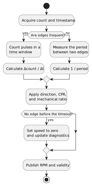
A hybrid estimator uses the period when edges are sparse and a time window when they become frequent, while keeping an explicit timeout for zero speed.
Also keep in mind that differentiation amplifies noise. Speed calculated from a quantized position often needs filtering, but an overly aggressive filter introduces delay. Once again, the compromise cannot be chosen outside the context of the control system.
A firmware speed estimator
For control or telemetry, the calculation can be encapsulated in a structure that retains the previous count and timestamp.
esp_timer_get_time() returns the elapsed time since startup in microseconds and is suitable for fine timing in both tasks and ISRs, with the caveat that it restarts from zero after deep sleep. (Espressif: ESP Timer)
#include <stdint.h>#include "esp_timer.h"typedef struct { int previous_count; int64_t previous_time_us; float filtered_rpm;} encoder_speed_estimator_t;static void encoder_speed_estimator_init(encoder_speed_estimator_t* estimator, int initial_count) { estimator->previous_count = initial_count; estimator->previous_time_us = esp_timer_get_time(); estimator->filtered_rpm = 0.0f;}static bool encoder_speed_estimator_update( encoder_speed_estimator_t* estimator, int current_count, int counts_per_revolution, float filter_alpha, float* rpm_out) { if (counts_per_revolution <= 0 || rpm_out == NULL) { return false; } int64_t const now_us = esp_timer_get_time(); int64_t const elapsed_us = now_us - estimator->previous_time_us; if (elapsed_us <= 0) { return false; } int const delta_count = current_count - estimator->previous_count; float const instant_rpm = ((float)delta_count * 60.0f * 1000000.0f) / ((float)counts_per_revolution * (float)elapsed_us); if (filter_alpha < 0.0f) { filter_alpha = 0.0f; } else if (filter_alpha > 1.0f) { filter_alpha = 1.0f; } estimator->filtered_rpm += filter_alpha * (instant_rpm - estimator->filtered_rpm); estimator->previous_count = current_count; estimator->previous_time_us = now_us; *rpm_out = estimator->filtered_rpm; return true;}With filter_alpha = 1.0f, no filtering is applied. Smaller values reduce variation but increase delay.
It is worth stating that an exponential filter cannot compensate for a badly chosen measurement window. If no counts arrive during a short window, the instantaneous speed becomes zero even when the shaft is still turning slowly.
MCPWM Capture for low-frequency speed
When edges are far apart, period measurement may provide more information than counting how many events fall inside a window.
MCPWM has a dedicated capture timer and GPIO-associated capture channels. The callback receives cap_value, the hardware timestamp of the edge, and cap_edge. (Espressif: MCPWM)
The following example captures rising edges on channel A:
#include <inttypes.h>#include <stdbool.h>#include <stdint.h>#include "driver/mcpwm_cap.h"#include "freertos/FreeRTOS.h"#include "freertos/queue.h"#define ENCODER_EVENTS_PER_REVOLUTION 600typedef struct { uint32_t period_ticks; uint32_t capture_value;} encoder_period_event_t;static mcpwm_cap_timer_handle_t capture_timer;static mcpwm_cap_channel_handle_t capture_channel;static QueueHandle_t period_queue;static uint32_t previous_capture_value;static bool previous_capture_valid;static bool encoder_capture_callback( mcpwm_cap_channel_handle_t channel, mcpwm_capture_event_data_t const* event_data, void* user_context) { (void)channel; QueueHandle_t queue = (QueueHandle_t)user_context; BaseType_t task_woken = pdFALSE; if (previous_capture_valid) { encoder_period_event_t const event = { .period_ticks = event_data->cap_value - previous_capture_value, .capture_value = event_data->cap_value, }; xQueueSendFromISR(queue, &event, &task_woken); } previous_capture_value = event_data->cap_value; previous_capture_valid = true; return task_woken == pdTRUE;}static esp_err_t encoder_capture_init(void) { period_queue = xQueueCreate(8, sizeof(encoder_period_event_t)); if (period_queue == NULL) { return ESP_ERR_NO_MEM; } mcpwm_capture_timer_config_t const timer_config = { .group_id = 0, .clk_src = MCPWM_CAPTURE_CLK_SRC_DEFAULT, .resolution_hz = 0, }; ESP_RETURN_ON_ERROR( mcpwm_new_capture_timer(&timer_config, &capture_timer), "encoder", "Unable to create capture timer" ); mcpwm_capture_channel_config_t const channel_config = { .gpio_num = ENCODER_GPIO_A, .prescale = 1, .flags.pos_edge = true, .flags.neg_edge = false, .flags.pull_up = true, }; ESP_RETURN_ON_ERROR( mcpwm_new_capture_channel(capture_timer, &channel_config, &capture_channel), "encoder", "Unable to create capture channel" ); mcpwm_capture_event_callbacks_t const callbacks = { .on_cap = encoder_capture_callback, }; ESP_RETURN_ON_ERROR( mcpwm_capture_channel_register_event_callbacks(capture_channel, &callbacks, period_queue), "encoder", "Unable to register capture callback" ); ESP_RETURN_ON_ERROR( mcpwm_capture_timer_enable(capture_timer), "encoder", "Unable to enable capture timer" ); ESP_RETURN_ON_ERROR( mcpwm_capture_channel_enable(capture_channel), "encoder", "Unable to enable capture channel" ); return mcpwm_capture_timer_start(capture_timer);}The task converts ticks into RPM. ENCODER_EVENTS_PER_REVOLUTION must represent the number of captured rising edges on channel A per revolution, not necessarily PCNT's x4 count:
static void encoder_period_task(void* argument) { (void)argument; uint32_t capture_resolution_hz; ESP_ERROR_CHECK(mcpwm_capture_timer_get_resolution(capture_timer, &capture_resolution_hz)); encoder_period_event_t event; while (true) { if (xQueueReceive(period_queue, &event, portMAX_DELAY) != pdTRUE) { continue; } if (event.period_ticks == 0) { continue; } float const event_frequency_hz = (float)capture_resolution_hz / (float)event.period_ticks; float const rpm = event_frequency_hz * 60.0f / (float)ENCODER_EVENTS_PER_REVOLUTION; ESP_LOGI("encoder", "period_ticks=%" PRIu32 ", rpm=%.2f", event.period_ticks, rpm); }}In CMakeLists.txt:
PRIV_REQUIRES esp_driver_mcpwmThis example measures only the frequency of rising edges on A. Direction can be derived by reading B at the instant of the edge or, more robustly, by retaining PCNT as the position decoder.
A practical combination may therefore be:
- PCNT for position and direction;
- MCPWM Capture for low-speed period measurement;
- a PCNT count window at high speed.
The measurement must also handle timeout. If no edge arrives for a sufficiently long interval, the last speed value cannot remain valid forever.
Using the Z channel without losing counts
The index can be used to correct position once per revolution. A naive solution is to clear PCNT immediately when Z changes state.
That may work, but it makes it harder to distinguish:
- the physical instant of the index;
- ISR latency;
- counts that occurred after the index;
- a false pulse on Z.
A more informative approach captures the current count in the ISR and applies a software offset in a task.
pcnt_unit_get_count() is permitted in ISR context by the current driver. (Espressif: PCNT)
typedef struct { int raw_count_at_index; int64_t timestamp_us;} encoder_index_event_t;static QueueHandle_t index_queue;static void encoder_index_isr(void* argument) { (void)argument; encoder_index_event_t event; if (pcnt_unit_get_count(encoder_unit, &event.raw_count_at_index) != ESP_OK) { return; } event.timestamp_us = esp_timer_get_time(); BaseType_t task_woken = pdFALSE; xQueueSendFromISR(index_queue, &event, &task_woken); if (task_woken == pdTRUE) { portYIELD_FROM_ISR(); }}The task can transform the raw count into a corrected position:
static portMUX_TYPE encoder_index_lock = portMUX_INITIALIZER_UNLOCKED;static int64_t encoder_position_offset;static int64_t encoder_get_corrected_position(void) { int raw_count; ESP_ERROR_CHECK(pcnt_unit_get_count(encoder_unit, &raw_count)); portENTER_CRITICAL(&encoder_index_lock); int64_t const offset = encoder_position_offset; portEXIT_CRITICAL(&encoder_index_lock); return (int64_t)raw_count + offset;}static void encoder_index_task(void* argument) { (void)argument; encoder_index_event_t event; while (true) { xQueueReceive(index_queue, &event, portMAX_DELAY); int64_t const expected_reference = 0; int64_t const new_offset = expected_reference - (int64_t)event.raw_count_at_index; portENTER_CRITICAL(&encoder_index_lock); encoder_position_offset = new_offset; portEXIT_CRITICAL(&encoder_index_lock); }}In a real system, I would not blindly accept every Z pulse. At a minimum, I would verify:
- that the index falls within a plausible window;
- that the direction is consistent;
- that no more than one index arrives in the same revolution;
- that the distance from the previous index is close to the expected counts per revolution;
- that the limit switch or homing phase identified the correct revolution.
The Z channel is a reference, not a guarantee against noise or mechanical errors.
Absolute encoders over SPI
When the sensor directly provides the angle over SPI, PCNT is not needed to read the absolute position.
The typical flow becomes:
- the task starts an SPI transaction;
- the sensor returns the angle register;
- the firmware checks parity and error bits;
- the value is converted into degrees or radians;
- the application handles the transition between the end and start of a revolution.
With a 14-bit value:
positions = 2^14 = 16384The nominal conversion is:
angle_degrees = value * 360 / 16384The AS5047D is one concrete example: it provides a 14-bit absolute angle over SPI and can also generate incremental ABI, PWM, and UVW signals. (ams OSRAM)
This combination supports an interesting architecture:
- SPI to obtain the absolute angle at startup;
- ABI connected to PCNT to follow motion with low latency;
- periodic SPI reads to verify or correct the incremental position.
This does not mean that the two paths are automatically equivalent. We must verify:
- offset and orientation;
- the configured ABI resolution;
- the sensor's internal delay;
- SPI transaction latency;
- magnetic-field diagnostics;
- possible parity errors;
- behavior across the 0/360-degree boundary.
A serial read is a sample. It does not observe every movement that occurred between two transactions. The incremental path, by contrast, can count edges continuously as long as it remains powered and configured.
Handling the transition between 359 and 0 degrees
A single-turn absolute sensor normally returns a value within a circular range. If we directly compare two samples near the wrap point, we may calculate an enormous jump:
previous sample = 16380current sample = 4naive delta = -16376The real movement may have been only eight counts forward.
We can calculate the shortest circular delta:
#include <stdint.h>static int32_t circular_delta(int32_t current, int32_t previous, int32_t modulus) { int32_t delta = current - previous; int32_t const half = modulus / 2; if (delta > half) { delta -= modulus; } else if (delta < -half) { delta += modulus; } return delta;}For a 14-bit sensor:
#define ABSOLUTE_MODULUS 16384static int64_t multi_turn_position;static uint16_t previous_absolute_sample;void process_absolute_sample(uint16_t current_sample) { int32_t const delta = circular_delta(current_sample, previous_absolute_sample, ABSOLUTE_MODULUS); multi_turn_position += delta; previous_absolute_sample = current_sample;}This logic reconstructs a multi-turn position only if the movement between two samples remains below half a revolution. If the shaft can turn faster, the firmware cannot determine how many wraps occurred.
Possible solutions include:
- increasing the sampling frequency;
- using the ABI output with PCNT;
- using a multi-turn absolute encoder;
- adding a dynamic model, while accepting that the result becomes an estimate.
Comparing SPI and ABI to detect errors
When a sensor exposes both interfaces, the absolute reading can be used to check the incremental path.
The flow may be:
- read the absolute angle at startup;
- initialize the PCNT offset;
- track motion through ABI;
- periodically read SPI;
- compare the two positions modulo one revolution;
- report or correct a difference beyond a threshold.
int32_t pcnt_mod = positive_modulo(pcnt_position, counts_per_revolution);int32_t absolute_as_pcnt = absolute_value * counts_per_revolution / absolute_modulus;int32_t error = circular_delta(absolute_as_pcnt, pcnt_mod, counts_per_revolution);An abrupt correction may propagate into the motor-control loop. In many systems it is preferable to:
- record the error first;
- verify that it persists across several samples;
- apply a gradual correction;
- enter a fault state if the divergence exceeds a safety threshold.
Encoders in motor control
In a control system, encoder position can close several loops.
Position loop
position_error = target_position - measured_positionSpeed loop
speed_error = target_speed - measured_speedCommutation
In a BLDC motor, rotor position can contribute to selecting which phases should be energized.
These problems do not have the same requirements.
A user-interface knob may tolerate one missed count. In a servo, the same error can become:
- oscillation;
- mechanical noise;
- position error;
- instability;
- a collision with a limit stop.
ESP-IDF's official DC motor speed-control example uses PCNT to decode the quadrature feedback encoder. (Espressif: motor control)
PCNT solves edge acquisition, not control design.
We still need to design:
- the loop frequency;
- the speed filter;
- controller gains;
- actuator limits;
- saturation handling;
- anti-windup;
- behavior when sensor feedback is lost;
- detection of a stalled or disconnected encoder.
A controller that always assumes valid feedback is not robust. If the motor is commanded but the count does not change, the firmware must determine whether the mechanism is stationary, stalled, or no longer producing a signal.
Organizing firmware into layers
The previous examples show several APIs, but the most important point is the architecture that connects them.
I would separate at least four layers:
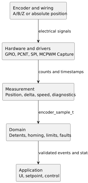
The driver exposes counts and timestamps, measurement turns them into samples, the domain applies product rules, and only the application updates the UI or controllers.
This separation prevents an ISR from needing to know which menu is currently displayed, or a PCNT driver from containing product-specific rules.
A common interface could be:
typedef struct { int64_t position; int32_t delta; float rpm; uint32_t invalid_transitions; bool index_seen; bool signal_fault; int64_t timestamp_us;} encoder_sample_t;The measurement task updates encoder_sample_t. Other components read or receive samples without knowing the acquisition method.
This makes it possible to replace:
- polling with PCNT;
- ABI with SPI;
- a mechanical knob with a magnetic sensor;
without rewriting all the application logic.
Detecting a stationary, disconnected, or inconsistent encoder
A count that does not change can mean several things:
- the shaft is stationary;
- the motor is stalled;
- the encoder is disconnected;
- A and B are stuck;
- the peripheral was never started;
- the electrical level does not cross the input threshold.
The firmware must compare the feedback with what the system expects.
typedef struct { int64_t last_motion_time_us; int64_t last_count; uint32_t invalid_transition_limit; int64_t no_motion_timeout_us;} encoder_monitor_t;bool encoder_monitor_update( encoder_monitor_t* monitor, int64_t current_count, uint32_t invalid_transitions, bool actuator_commanded) { int64_t const now_us = esp_timer_get_time(); if (current_count != monitor->last_count) { monitor->last_count = current_count; monitor->last_motion_time_us = now_us; } if (invalid_transitions > monitor->invalid_transition_limit) { return false; } if (actuator_commanded && now_us - monitor->last_motion_time_us > monitor->no_motion_timeout_us) { return false; } return true;}This logic is not universal. An axis may have inertia, backlash, or phases in which a command does not immediately produce motion. Thresholds must be derived from the real system.
Do not make logging part of the timing path
Logs are extremely useful in tasks. Inside an ISR or a high-frequency callback, they can alter the very behavior we are trying to observe.
A better strategy is to collect diagnostic counters:
typedef struct { uint32_t valid_forward; uint32_t valid_backward; uint32_t invalid_transitions; uint32_t queue_overflows; uint32_t index_events;} encoder_diagnostics_t;A low-frequency task can print them once per second:
forward=4218 backward=17 invalid=3 queue_overflow=0 index=12The information remains readable, and the timing-critical path is not filled with formatting and serial I/O.
Cache, IRAM, and event latency
Hardware counting reduces dependence on the scheduler, but it does not make every event instantaneous.
PCNT callbacks run from an interrupt. By default, their execution may be delayed while the cache is disabled during some Flash operations.
ESP-IDF exposes two relevant options:
CONFIG_PCNT_ISR_IRAM_SAFECONFIG_PCNT_CTRL_FUNC_IN_IRAMThe first allows the driver's ISR to run while the cache is disabled, provided that callbacks, data, and called functions are placed in accessible memory. The second places selected control functions:including read, start, stop, and clear:in IRAM, according to the documentation for the ESP-IDF version in use. (Espressif: PCNT)
I would not enable them by habit.
For a knob, a delay in event processing is usually irrelevant: the hardware counter continues capturing edges.
For motor control or a protection event, however, we must analyze:
- interrupt priority;
- critical-section duration;
- Flash operations;
- logging;
- Wi-Fi and Bluetooth activity;
- high-priority tasks;
- available IRAM;
- event frequency.
Placing code in IRAM reduces some latency, but it consumes a limited resource. The choice should follow a measurable requirement, not an option enabled “just to be safe.”
Light sleep, deep sleep, and loss of position
An encoder used in a user interface can also wake the system.
The official EC11 example configures wake-up on a low level because the signal is normally held high and the contact pulls it to ground. (Espressif: PCNT example)
This does not imply that every transition occurring during sleep is retained.
At least four aspects must be distinguished:
- which GPIO can wake the chip;
- which power domains and peripherals remain active;
- which pin state is observed on wake-up;
- where the software position is stored.
In light sleep, some resources may remain active depending on the target and configuration. In deep sleep, by contrast, much of the system is powered down and execution effectively restarts from a new boot.
An incremental encoder cannot recover absolute position by itself after power loss.
The alternatives include:
- a homing procedure;
- a Z index and reference search;
- periodic storage in non-volatile memory;
- an absolute encoder;
- a multi-turn sensor;
- a battery-backed or always-powered domain, where available.
Saving every count to Flash is not a good solution: it increases latency, power consumption, and memory wear. It is better to save at reasoned intervals, during a controlled shutdown, or to use a storage technology suited to the required update frequency.
Common mistakes
Confusing PPR, CPR, and x4 counts
The calculated angle is wrong by a factor of two or four.
Confusing counts and detents
The knob moves several units per click or appears insufficiently responsive.
Connecting A and B without a defined level
Floating inputs produce random transitions. Pull-ups, pull-downs, or an output that actively drives both levels are required.
Connecting 5 V, 12 V, or 24 V directly to a GPIO
A signal that appears to work may still exceed the chip's electrical limits. Proper level adaptation is required.
Treating the glitch filter as debounce
PCNT continues counting bounce pulses that are longer than the configured threshold.
Using an RC filter that is too slow
The edges cross the threshold slowly, A and B lose their phase relationship, and valid pulses are removed.
Logging from the callback
Behavior depends on the logging backend and may introduce latency, contention, or watchdog problems.
Forgetting the limit watch points
accum_count cannot correctly compensate for overflows if the limits do not generate the required events.
Using .accum_count = true instead of the nested flag
In the current structure, the flag is nested:
.flags.accum_count = trueThe flat form does not match the definition of pcnt_unit_config_t in ESP-IDF 6.0.2. (Espressif: PCNT header)
Copying code written for the legacy driver
Examples based on driver/pcnt.h are not directly compatible with ESP-IDF 6.0, where the previous driver was removed. (Espressif: 6.0 migration guide)
Failing to verify direction
Swapping A and B, or observing the shaft from the opposite side, reverses the direction.
Failing to handle negative modulo values
In C, the remainder of a negative division may be negative. To obtain an angle in the range [0, counts_per_revolution), we can normalize it as follows:
int normalize_count(int count, int counts_per_revolution) { int normalized = count % counts_per_revolution; if (normalized < 0) { normalized += counts_per_revolution; } return normalized;}Trying to fix an electrical problem in firmware
If the signal exceeds the thresholds, oscillates, or contains interference, adding arbitrary delays to the decoder may hide the issue without solving it.
Diagnosing the real signal
A logic analyzer is often the most useful tool. For analog levels, slow edges, and overshoot, an oscilloscope is required instead.
A and B should be observed together while checking:
- minimum and maximum levels;
- the state sequence;
- pulse duration;
- duty cycle;
- bounce;
- transitions per detent;
- behavior during reversal;
- maximum frequency;
- invalid state jumps;
- interference while motors, radios, and power supplies are active.
A logic analyzer shows the digital sequence well. It does not necessarily show how close the signal is to the electrical threshold.
An input may appear as 0 or 1 in the capture and still suffer from:
- edges that are too slow;
- ringing;
- overshoot;
- undervoltage;
- noise around the threshold;
- ground problems.
For an absolute magnetic encoder, I would also check:
- magnet centering;
- axial distance;
- tilt;
- field diagnostics;
- error bits;
- parity;
- offset;
- nonlinearity;
- the 0/360-degree transition.
Testing must be performed on the real product and under the worst expected conditions:
- maximum speed;
- longest cable;
- temperature limits;
- motor under load;
- active PWM;
- active Wi-Fi or Bluetooth;
- the noisiest power-supply condition.
A breadboard with short wires is useful for getting started. It does not certify final behavior.
Choosing the architecture
| Application | Typical encoder | Recommended acquisition |
|---|---|---|
| Menu or slow parameter adjustment | Mechanical with detents | State machine or PCNT |
| Volume control | Mechanical with detents | PCNT and conversion into logical events |
| Motor speed measurement | Optical or magnetic incremental | Windowed PCNT or MCPWM Capture |
| Position servo | High-resolution incremental or absolute | PCNT or a dedicated interface |
| Position known immediately after startup | Magnetic, optical, or inductive absolute | SPI, SSI, BiSS, or a device-specific protocol |
| Long industrial cable | Differential line driver | Differential receiver and PCNT |
| Target without PCNT, slow knob | Mechanical | Polling, GPIO interrupts, or GPTimer |
| Dirty or humid environment | Magnetic or inductive | SPI, ABI, or a dedicated interface |
| Multi-turn system | Multi-turn absolute or homing | Serial interface and revolution tracking |
The best choice is not the encoder with the largest number printed in its datasheet.
It must simultaneously satisfy:
- required accuracy;
- useful resolution;
- maximum speed;
- startup behavior;
- environment;
- cable length;
- noise immunity;
- latency;
- mechanical lifetime;
- cost;
- microcontroller resources;
- fault-handling strategy.
For a UI, simplicity and mechanical feel may matter more than absolute accuracy. For an axis, repeatability, latency, and diagnostics become central.
Design checklist
Before finalizing the schematic and firmware, it is useful to answer these questions:
- Is the encoder incremental or absolute?
- Does the declared value mean PPR, CPR, cycles, lines, or x4 counts?
- How many counts does it actually produce per revolution?
- How many counts does it produce per detent?
- What is the maximum edge frequency?
- What accuracy is required on the real axis?
- Must the motion remain known after a reset or power loss?
- Is the output contact-based, push-pull, open-collector, or differential?
- What voltage levels does it produce?
- Is a receiver, buffer, or level shifter required?
- Are the selected pins compatible with the target, boot process, and sleep modes?
- Do the lines have defined pull-up or pull-down states?
- Is the disturbance electrical, mechanical, or both?
- Does the filter preserve the shortest valid pulse?
- Is PCNT available on the selected target?
- Does the ESP-IDF version use the current driver or the legacy one?
- Are the counter limits wide enough?
- Are
accum_countand the limit watch points configured correctly? - Is a callback necessary, or is periodically reading the count sufficient?
- Do callbacks use only ISR-compatible APIs?
- How is the raw count converted into user events?
- How is speed estimated?
- What happens during light sleep and deep sleep?
- How is a disconnected or stalled encoder detected?
- Does the sampling frequency preserve every quadrature state?
- Are invalid transitions counted and diagnosed?
- Is the Z channel validated within a plausible window?
- Does the speed estimate handle a timeout when no edges arrive?
- Has the signal been measured at maximum speed?
- Does testing include motors, radios, and the real power-supply condition?
Not every question requires a complex solution. Every question should, however, have an explicit answer.
Conclusion
An encoder is not difficult because of the number of wires. It becomes difficult when we require every layer of the system to remain coherent.
The mechanics produce motion. The sensing principle turns it into a physical variation. The electronics generate a signal. The wiring must preserve its integrity. The decoder reconstructs direction and count. Finally, the firmware assigns meaning to the position.
Confusing these layers leads to the most common mistakes: using debounce to compensate for noisy wiring, increasing a filter to mask incompatible voltage levels, treating resolution as accuracy, or using a mechanical knob as feedback for a controller that requires deterministic reliability.
With ESP-IDF, the design can begin with a software state machine for a slow knob, move to interrupts or GPTimer when more controlled acquisition is needed, and arrive at PCNT when counting must continue in hardware. For low-frequency speed measurement, MCPWM Capture also allows the period between edges to be measured directly.
PCNT remains the natural solution for incremental encoders when the target provides it. It counts edges in hardware, uses the second signal to determine direction, filters short glitches, supports fixed-step notifications, and can extend the count beyond the hardware-register limits.
It does not perform magic.
PCNT does not replace the datasheet, electrical design, level compatibility checks, semantic debounce, or verification with real instruments. With ESP-IDF 6.0, the current driver/pulse_cnt.h driver must also be used, including less obvious details such as .flags.accum_count and the limit watch points.
In substance, the encoder provides information about motion. Reliability comes from how the system decides to acquire, validate, and transform that information into state.
Sources
The general theory and the distinction between incremental and absolute encoders were checked against Renishaw's technical documentation. Quadrature behavior was compared with US Digital's guide. (Renishaw) (US Digital)
The characteristics of mechanical and magnetic encoders were compared with the Bourns PEC11R and ams OSRAM AS5047D datasheets. (Bourns) (ams OSRAM)
The ESP-IDF sections are based on the PCNT, GPIO, GPTimer, MCPWM Capture, and ESP Timer documentation, together with the official rotary_encoder example, the ESP-IDF 6.0 migration guide, and the public driver-header definition. (Espressif: PCNT) (Espressif: PCNT example) (Espressif: 6.0 migration guide) (Espressif: PCNT header) (Espressif: GPIO) (Espressif: GPTimer) (Espressif: MCPWM) (Espressif: ESP Timer)
Image credits
- Cover image: VW Rot enc.jpg by Lambtron, Wikimedia Commons, licensed under CC BY-SA 4.0. The image was converted to WebP for the site layout; the adapted version remains available under the same license.

Last updated
2026-07-28.
Article source content/blog/rotary_encoders_esp32_esp_idf_pcnt.