Abstract
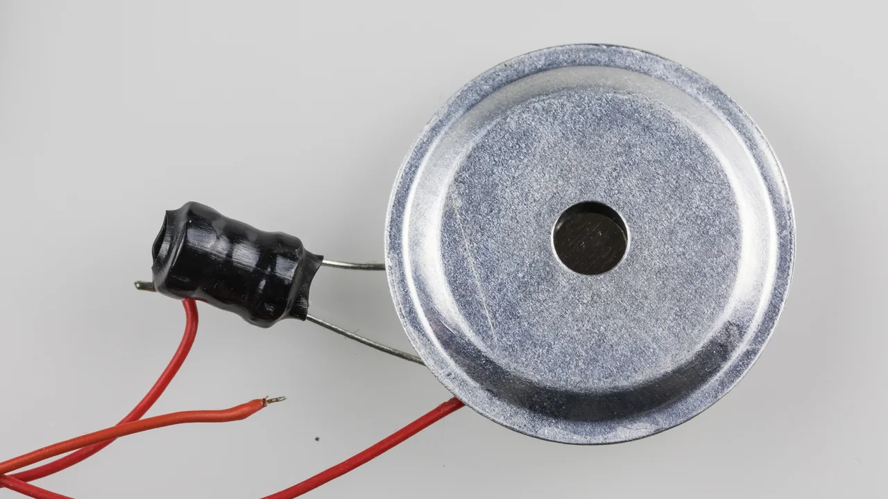
While developing physical interfaces, I have repeatedly used a buzzer to confirm a command, report an error, or draw the user's attention.
At first glance, the problem seems trivial: connect the component to a GPIO, generate a square wave, and the sound is ready.
Not quite.
Behind two terminals there may be very different technologies and circuits. A buzzer may be piezoelectric or magnetic, include an oscillator or require an external signal, draw only a few milliamperes or need a transistor, work well around a single resonant frequency, or reproduce a short melody whose loudness changes noticeably from note to note.
Then there is the firmware side. Generating one tone is simple; building a sound engine that respects tempo, rests, articulation, event priority, and concurrency with the other tasks requires a few more design decisions.
I therefore decided to rebuild the topic from the physical principle up to a complete implementation with ESP32 and ESP-IDF. We will cover:
- how sound is produced;
- the difference between piezoelectric and magnetic buzzers;
- the distinction between indicators with an internal oscillator and externally driven transducers;
- how to read a datasheet;
- when a GPIO can drive the device directly and when a power stage is required;
- how to generate tones with LEDC;
- how to represent notes, tempo, rests, and articulation;
- how to build melodies and acoustic signals without blocking the application;
- which limits separate a buzzer from a real audio system.
The goal is not merely to make the component beep. It is to understand which information we are entrusting to sound, then design the hardware and firmware so that information remains recognizable, repeatable, and consistent with the rest of the system.
Scope of the article
The electronics discussion remains general and can be applied to different microcontrollers.
The firmware examples instead use ESP32 and ESP-IDF 6.0.2, with the handle-based APIs and current drivers available at the time of writing. We will therefore not use the Arduino tone() function.
We will focus on the two types most commonly found in embedded products today:
- piezoelectric buzzers;
- magnetic or electromagnetic buzzers.
Other mechanical and electromechanical devices exist, along with sirens and more complex sounders. Their operating principle may be related, but power, supply, and safety requirements deserve a separate analysis.
It is also worth clarifying that the schematics shown here are conceptual. Resistor, transistor, diode, voltage, and duty-cycle values must be sized according to the datasheet of the actual component selected.
What is a buzzer?
A buzzer is an acoustic signaling device.
It receives electrical energy and turns it into mechanical vibration. That vibration moves the air and creates a pressure variation that our ears perceive as sound.
In firmware, a buzzer is often treated as a binary output:
0 -> silence1 -> soundThis representation is sufficient for some active indicators, but it does not describe everything that may happen.
With an externally driven transducer, we can control at least:
- frequency;
- duration;
- rhythm;
- duty cycle;
- drive voltage;
- note sequence;
- rests;
- an approximate envelope;
- acoustic-signal priority.
The buzzer does not interpret the meaning of the sound. The firmware decides whether two short pulses mean confirmation, an alternating pattern signals an error, or a melody accompanies device startup.
How sound is produced
An ideal tone is a periodic variation in air pressure.
Frequency tells us how many times the phenomenon repeats in one second:
frequency = cycles / secondThe unit is the hertz:
1 Hz = 1 cycle per secondA 440 Hz signal therefore completes 440 periods in one second.
The period is the inverse of frequency:
T = 1 / fFor a 1 kHz tone:
T = 1 / 1000 = 1 msWith a 50% square wave, the signal remains high for roughly 500 µs and low for another 500 µs.
Pitch, loudness, and timbre
In musical and perceptual terms, it is useful to separate three aspects.
Pitch depends mainly on the fundamental frequency. A higher frequency is usually perceived as a higher note.
Loudness depends on the sound pressure produced and is often expressed as SPL, or Sound Pressure Level. A value stated in a datasheet is meaningful only together with its measurement conditions: distance, voltage, frequency, waveform, and environment.
Timbre depends instead on the distribution of harmonics and on the mechanical behavior of the transducer and its enclosure.
A square wave does not contain only the fundamental frequency. It also contains odd harmonics. This is why a buzzer driven with PWM sounds harsher than a sine wave at the same fundamental frequency.
That is not necessarily a problem. In interface signals, a waveform rich in harmonics may make a beep easier to recognize. However, the frequency configured in the timer should not be confused with the complete spectral content emitted by the component.
Two different classifications
One of the main sources of confusion is that buzzers are classified using terms that describe different aspects.
The first classification concerns the physical technology:
- piezoelectric;
- magnetic or electromagnetic.
The second concerns the drive method:
- indicator with an internal oscillator;
- externally driven transducer.
In common usage, these are often called active buzzers and passive buzzers, respectively.
The terminology is useful, but it is not always consistent across manufacturers and distributors. When in doubt, it is therefore better to search the datasheet for expressions such as:
indicatorbuilt-in oscillating circuitself drivetransducerexternal driverated frequencyTechnology and drive method are not the same thing.
A piezoelectric buzzer may include an oscillator. Another piezoelectric device may require an external square wave. The same is true for different magnetic buzzers. Same Sky explicitly distinguishes an indicator, which generates a tone when DC voltage is applied, from a transducer, which requires an external waveform. Murata makes a similar distinction between buzzers with a built-in oscillation circuit and externally driven sounders. (Same Sky) (Murata)
| Technology | Drive method | Typical behavior |
|---|---|---|
| Piezoelectric | Indicator / active | emits a predefined tone when powered with DC |
| Piezoelectric | Transducer / passive | frequency depends on the external signal |
| Magnetic | Indicator / active | integrates the circuitry required to generate the tone |
| Magnetic | Transducer / passive | requires alternating current through the coil |
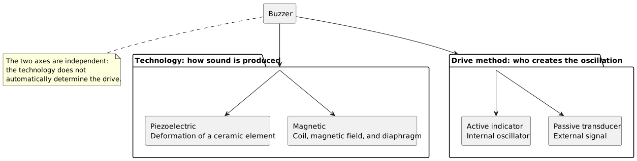
Technology and drive method answer different questions. First identify how the component produces sound, then determine whether the oscillation is generated internally or must come from the external circuit.
Piezoelectric buzzers
A piezoelectric element changes shape slightly when an electric field is applied.
In a buzzer, the piezoelectric material is normally bonded to a metal disc. Applying an alternating voltage bends the disc first in one direction and then in the other. That deformation moves the air and produces sound. (Murata)
From an electrical point of view, a piezo element is often approximated as a capacitive load.
This means that current also depends on frequency:
I = C * dV/dtFor a sine wave, we can reason in terms of capacitive reactance:
Xc = 1 / (2 * pi * f * C)As frequency increases, reactance decreases and reactive current may increase.
This approximation does not describe the whole mechanical behavior or resonance, but it is useful for understanding why a piezo should not be treated as a simple resistor.
Typical advantages
Piezoelectric buzzers may offer:
- relatively low power consumption;
- a thin structure;
- no moving coil;
- good sound pressure near the design frequency;
- the possibility of using high peak-to-peak voltages with dedicated drivers;
- good mechanical longevity.
Typical limitations
However, we must consider:
- an often irregular frequency response;
- loudness that strongly depends on resonance;
- capacitive behavior;
- the importance of the acoustic cavity;
- the required drive voltage;
- limited quality when reproducing complex audio.
TDK, for example, offers piezoelectric transducers with nominal frequencies of 2 kHz, 4 kHz, or 5 kHz. Two models with the same diameter may produce different sound levels because of enclosure height and acoustic construction. The PS1240P02CT3 is specified at a minimum of 60 dB, 4 kHz, and 3 V0-p, while the taller PS1240P02BT is specified at 70 dB under the same nominal conditions. These are characteristics of those specific components, not universal rules. (TDK) (TDK)
Magnetic buzzers
A magnetic buzzer uses a coil.
When current flows through the coil, it generates a magnetic field that moves a ferromagnetic diaphragm. When the current is interrupted, the diaphragm returns toward its resting position. Repeating the process periodically creates vibration and therefore sound. (Same Sky)
From an electrical point of view, the component behaves approximately like a resistance in series with an inductance.
Current cannot change instantaneously. When the transistor driving the coil turns off, the inductance tries to keep the current flowing and may generate an overvoltage.
The solution?
A recirculation path, usually implemented with a flyback diode or another suitable clamp circuit.
Typical advantages
Magnetic buzzers may offer:
- operation at low voltages;
- good sound pressure in a compact package;
- useful response at relatively low frequencies;
- a drive approach conceptually similar to that of other small inductive loads.
Typical limitations
However, we must consider:
- generally higher current than many piezo devices;
- the presence of a coil;
- the need to manage inductive overvoltage;
- heating and duty cycle;
- loudness that depends on the available current.
Same Sky reports, as a general trend, that magnetic buzzers operate at lower voltages and higher currents than piezo devices. Its catalog also includes small 3 V magnetic transducers that may require currents in the order of 100 mA: clearly incompatible with direct GPIO drive. (Same Sky) (Same Sky)
Active indicator and passive transducer
Indicator with an internal oscillator
An indicator includes the circuit that generates the oscillation.
Its logical connection resembles that of a load being switched on and off:
power applied -> soundpower removed -> silenceThe firmware mainly controls:
- turning it on;
- turning it off;
- duration;
- rhythm;
- number of pulses.
It cannot freely control pitch because the frequency is determined by the internal circuit.
Some indicators already include a pattern or intermittent tone. Here too, the datasheet is the only reliable source.
Externally driven transducer
A transducer does not generate the tone on its own.
It requires a periodic signal:
GPIO / PWM -> driver -> transducer -> soundThe signal frequency determines the fundamental frequency of the tone. This makes it possible to:
- choose different notes;
- create sweeps;
- build melodies;
- change cadence;
- create recognizable signals for different events.
A transducer offers more freedom, but it transfers responsibility for generating the waveform correctly to the firmware and hardware.
How to identify the component
The correct method is to read the part number printed on the component and retrieve its datasheet.
When the code is unavailable, we can gather some clues, but we cannot reach absolute certainty.
Presence of a + symbol
Many active indicators are polarized and marked with a + symbol.
However, some transducers may also have a recommended polarity to preserve phase consistency or match the manufacturer's measurement method. The symbol alone is therefore not enough to identify the internal circuit.
Testing with DC voltage
An active indicator compatible with the applied voltage should produce a continuous tone.
A passive transducer may instead produce only a click during connection or disconnection because DC voltage creates one initial deformation, not periodic movement.
This test should only be performed when at least the plausible operating voltage of the device is known. Applying 5 V to a part designed for a lower voltage is not a prudent identification method.
Measuring resistance
A magnetic transducer normally shows a DC resistance associated with its coil.
A piezo may instead appear open-circuit in a DC measurement because it behaves primarily as a capacitance.
An indicator with integrated electronics may produce readings that depend on polarity and the internal circuit.
This measurement also provides a clue, not a complete identification.
The problem with ready-made modules
Many modules sold for microcontrollers include:
- a transistor;
- a base or gate resistor;
- an LED;
- a pull-down resistor;
- a three-pin connector;
- an active or passive buzzer.
In that case, the behavior of the module does not necessarily match that of the component mounted on it.
Before writing the firmware, we need to understand whether the control pin:
- powers the buzzer directly;
- drives a transistor;
- is active high;
- is active low;
- accepts PWM;
- supports only an on/off command.
Reading the datasheet
The label “5 V buzzer” is not enough to design the circuit.
Rated voltage
Rated voltage is the value used to specify particular performance characteristics.
It may be expressed as:
VDC;Vrms;V0-p;Vp-p.
These quantities are not interchangeable.
For a unipolar square wave from 0 V to 3.3 V:
V0-p = 3.3 VVp-p = 3.3 VWith differential drive that alternately places the two terminals at 0 V and 3.3 V in opposition, the voltage seen by the component may swing from +3.3 V to -3.3 V:
Vp-p = 6.6 VThis is one reason a bridge can increase the sound pressure of a piezo device without increasing the supply voltage.
Operating voltage range
The operating range indicates the voltages within which the manufacturer expects the device to function.
It should not be confused with the absolute maximum voltage. Remaining below the maximum does not guarantee that the sound will be correct, nor that the component can operate continuously under those conditions.
Rated or resonant frequency
The rated frequency is often close to the region in which the component produces its highest sound pressure.
Driving the buzzer far from that frequency may reduce the volume considerably.
This becomes obvious with melodies: a theoretically correct scale may sound unbalanced because some notes fall close to resonance while others lie in inefficient regions.
Sound Pressure Level
The SPL value must be read together with:
- measurement distance;
- voltage;
- frequency;
- waveform;
- temperature;
- minimum or typical tolerance.
A specification such as:
70 dB(A) min @ 10 cm, 4 kHz, 3 V0-p, square wavedoes not mean that the component always produces 70 dB.
Changing the distance, frequency, mounting, or voltage changes the result.
Current or power consumption
For an active indicator, the datasheet may state the current draw directly.
For a magnetic transducer, we need to consider the impedance of the coil and the drive frequency.
For a piezo device, the datasheet may specify capacitance, impedance, or current under particular conditions.
Current is one of the parameters that determines whether the device can be driven directly or requires an external stage.
Duty cycle and maximum activation time
Some buzzers are designed for intermittent operation.
The datasheet may specify:
- maximum duty cycle;
- maximum tone duration;
- required pause time;
- reference temperature.
An alarm that runs for a few seconds is not equivalent to a device left active for hours.
Temperature and mounting
Acoustic response also depends on:
- temperature;
- humidity;
- soldering method;
- enclosure opening;
- position on the PCB;
- presence of gaskets;
- the product cavity.
The component datasheet cannot automatically predict the acoustics of our enclosure.
The acoustic cavity is part of the design
Sound does not end at the surface of the buzzer.
The product enclosure creates a cavity, introduces resonances, and may attenuate or amplify particular frequencies.
A buzzer that is very loud on the bench may become weak once enclosed in a case. Possible causes include:
- an acoustic opening that is too small;
- excessive distance from the opening;
- an unfavorable internal volume;
- absorptive material;
- a gasket that blocks the diaphragm;
- mounting stress that distorts the component;
- water or dust in front of the opening.
Murata shows that the diaphragm and cavity have their own resonant frequencies and that the acoustic circuit contributes to sound pressure. TDK likewise highlights substantial differences between parts with a similar diameter but different heights and internal structures. (Murata) (TDK)
The practical conclusion is simple: the buzzer must be evaluated in the assembled product, not only on a breadboard.
Direct GPIO drive
Connecting a buzzer directly to a GPIO can work only when all electrical conditions are compatible.
We need to verify:
- required voltage;
- peak current;
- average current;
- capacitive or inductive nature of the load;
- actual GPIO high-level voltage;
- behavior during reset;
- presence of transients;
- activation duration.
There is no rule according to which “a small buzzer” is automatically safe for the pin.
A low-capacitance external piezo may require little average current but still draw current pulses at the edges. A magnetic transducer may require tens of milliamperes. An indicator may be designed for 5 V and fail to reach the desired sound pressure at 3.3 V.
For a prototype, trying a direct connection may be tempting. For a repeatable design, I prefer to separate the GPIO from the load with a transistor whenever current, voltage, or transients are not clearly within limits.
Driving an indicator with a transistor
A low-side connection with an N-channel MOSFET is simple and makes the firmware independent of buzzer current, within the transistor limits.
+V_BUZZER | BUZZER | +------ drain N-MOSFETGPIO --- Rg ----- gate | Rpd |GND -------------+------ sourceThe Rpd resistor keeps the MOSFET off during reset. The gate resistor limits transients and damps possible oscillations.
The MOSFET must be selected by considering:
- gate voltage available at
3.3 V; - load current;
- drain-source voltage;
RDS(on)at the actual gate voltage;- package and power dissipation.
With an NPN BJT, the base current must instead be sized to bring the transistor into saturation without overloading the GPIO.
Logic polarity
With a low-side connection:
GPIO high -> transistor on -> buzzer poweredGPIO low -> transistor off -> silenceA commercial module may invert this logic. It is therefore better to hide the electrical level behind functions such as:
active_buzzer_on();active_buzzer_off();instead of scattering gpio_set_level() calls throughout the application.
Driving a magnetic transducer
For a magnetic transducer, the transistor must switch the coil current at the tone frequency.
+V | MAGNETIC TRANSDUCER | +---------- drain/collector | transistor +----|<|----+ diode | GNDThe drawing is conceptual only: the diode orientation must prevent conduction during normal operation while providing a path for the inductive current when the transistor turns off.
Same Sky explicitly recommends a clamp diode in the typical circuit for a magnetic transducer. (Same Sky)
A conventional diode reduces the overvoltage, but it also slows the decay of current through the coil. Some acoustic or high-speed designs use different clamps to obtain faster demagnetization. For a common buzzer, however, the circuit recommended by the manufacturer remains the correct starting point.
Driving a piezoelectric transducer
A piezo device does not normally require the flyback diode used with a coil.
The main problem is instead charging and discharging the capacitance of the component.
A simple single-ended driver may use a transistor and a resistor that returns the terminal to its resting state when the transistor is open. Same Sky shows this topology and notes that the resistor dissipates power; Murata publishes different circuits for externally driven sounders and self-drive devices. (Same Sky) (Murata)
+V | PIEZO | +------ switch ------ GND | Rreset | +V or GNDThe actual connection depends on the circuit and datasheet.
Push-pull drive
Two complementary outputs can apply a larger differential voltage across the piezo:
phase 1: A = 3.3 V, B = 0 V -> Vpiezo = +3.3 Vphase 2: A = 0 V, B = 3.3 V -> Vpiezo = -3.3 VThe total swing becomes:
Vp-p = 6.6 VThis may increase sound pressure, but it requires perfectly coordinated outputs. A fault that causes both outputs to conflict through an unsuitable driver may result in high current.
For a real design, it is preferable to use:
- a push-pull driver designed for the load;
- an integrated bridge;
- two synchronized hardware channels;
- the topologies recommended by the manufacturer.
Same Sky describes several techniques for increasing the peak-to-peak voltage applied to a piezo device, including bridge drive and circuits using an inductor. (Same Sky)
DC bias on piezo devices
A piezoelectric transducer is normally excited with an alternating voltage.
Applying a permanent DC component may:
- shift the mechanical operating point;
- reduce the available displacement in one direction;
- increase stress on the material;
- violate the conditions under which the manufacturer specifies the maximum voltage.
Some datasheets explicitly state the input limit with the note “without DC bias.” TDK uses this condition for its PS-series piezoelectric transducers. (TDK)
A unipolar square wave between 0 V and 3.3 V contains a positive average component. The device may still be designed for this type of drive, but we should not assume so without reading the datasheet.
Differential drive that alternates positive and negative voltage across the piezo terminals instead creates a more symmetrical mechanical stress and uses a larger peak-to-peak voltage.
The correct solution therefore depends on:
- transducer construction;
- permitted voltage;
- recommended circuit;
- frequency;
- duration;
- target sound pressure.
Power supply, ground, and interference
A buzzer may introduce both electrical and acoustic interference.
On the electrical side, we need to consider:
- current pulses;
- ground return paths;
- coil transients;
- harmonics from PWM edges;
- coupling into ADCs and analog sensors;
- power-supply noise;
- radiated emissions from the connections.
Common good practices include:
- a bypass capacitor close to an active indicator;
- placing the transistor near the load;
- a short ground path;
- placing the diode close to the coil;
- separation from sensitive analog nodes;
- no faster slew rate than necessary, where controllable;
- a gate or series resistor to damp edges;
- verification with an oscilloscope.
A beep that causes a reset or changes an ADC reading is not a melody problem. It is a power-supply, layout, or electromagnetic-compatibility problem.
Which ESP32 peripheral should we use?
On ESP32, we can manage a buzzer in several ways.
| Requirement | Peripheral or approach |
|---|---|
| Turn an active indicator on and off | GPIO |
| Generate a stable tone | LEDC |
| Change frequency over time | LEDC + task or timer |
| Schedule events precisely | GPTimer or esp_timer |
| Reproduce simple sampled audio | PWM Audio |
| Reproduce more complete digital audio | I2S + codec/amplifier |
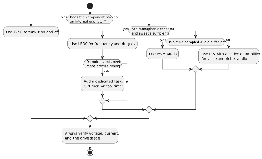
The choice starts with the component and the required acoustic result. Timers and tasks schedule events, while LEDC continues to generate the tone edges in hardware.
LEDC was designed for LED control, but Espressif specifies that it can also generate PWM for other devices. It lets us configure frequency and duty-cycle resolution, change frequency at runtime, and suspend the output. (Espressif Systems)
For a monophonic melody, it is therefore a natural choice:
LEDC generates the waveforma task decides when to change notethe electrical driver drives the buzzerGPTimer and esp_timer are not required to produce every edge of the tone directly: that is LEDC's job. They are instead useful for scheduling musical events or effects with more precise timing. Espressif recommends GPTimer when more real-time behavior or configurable resolution is required, while esp_timer provides microsecond-resolution software timers with one-shot or periodic callbacks. (Espressif Systems) (Espressif Systems)
Minimal example: active indicator
Suppose we use an indicator powered through a low-side MOSFET. The GPIO therefore controls the gate and does not supply the buzzer current directly.
#include "driver/gpio.h"#include "esp_check.h"#include "esp_err.h"#define BUZZER_ENABLE_GPIO GPIO_NUM_18static char const* TAG = "active_buzzer";esp_err_t active_buzzer_init(void) { gpio_config_t const config = { .pin_bit_mask = 1ULL << BUZZER_ENABLE_GPIO, .mode = GPIO_MODE_OUTPUT, .pull_up_en = GPIO_PULLUP_DISABLE, .pull_down_en = GPIO_PULLDOWN_DISABLE, .intr_type = GPIO_INTR_DISABLE, }; ESP_RETURN_ON_ERROR(gpio_config(&config), TAG, "Unable to configure the buzzer GPIO"); return gpio_set_level(BUZZER_ENABLE_GPIO, 0);}esp_err_t active_buzzer_on(void) { return gpio_set_level(BUZZER_ENABLE_GPIO, 1);}esp_err_t active_buzzer_off(void) { return gpio_set_level(BUZZER_ENABLE_GPIO, 0);}A blocking beep can be implemented as follows:
#include "freertos/FreeRTOS.h"#include "freertos/task.h"esp_err_t active_buzzer_beep(uint32_t duration_ms) { ESP_RETURN_ON_ERROR(active_buzzer_on(), TAG, "Unable to activate the buzzer"); vTaskDelay(pdMS_TO_TICKS(duration_ms)); return active_buzzer_off();}The code works, but it blocks the calling task for the whole duration of the sound.
That may be acceptable in a test or a dedicated task. It is not a good idea inside a task that must also manage networking, input, a display, or motor control.
Signaling patterns with an active indicator
Even without frequency control, we can encode information through rhythm.
typedef struct { uint16_t on_ms; uint16_t off_ms;} active_buzzer_pulse_t;static active_buzzer_pulse_t const success_pattern[] = { {.on_ms = 70, .off_ms = 70}, {.on_ms = 140, .off_ms = 0},};static active_buzzer_pulse_t const error_pattern[] = { {.on_ms = 250, .off_ms = 120}, {.on_ms = 250, .off_ms = 120}, {.on_ms = 250, .off_ms = 0},};esp_err_t active_buzzer_play_pattern(active_buzzer_pulse_t const* pattern, size_t pulse_count) { if (pattern == NULL || pulse_count == 0) { return ESP_ERR_INVALID_ARG; } for (size_t i = 0; i < pulse_count; ++i) { ESP_RETURN_ON_ERROR(active_buzzer_on(), TAG, "Unable to activate the buzzer"); vTaskDelay(pdMS_TO_TICKS(pattern[i].on_ms)); ESP_RETURN_ON_ERROR(active_buzzer_off(), TAG, "Unable to deactivate the buzzer"); if (pattern[i].off_ms > 0) { vTaskDelay(pdMS_TO_TICKS(pattern[i].off_ms)); } } return ESP_OK;}The logic is simple:
success -> two short pulseserror -> three long pulsesalarm -> repeated sequenceThis is already a form of composition, even though it is not musical. The variable is not pitch, but temporal structure.
Generating a tone with LEDC
For a passive transducer, we need to generate a periodic waveform.
We will use LEDC with:
- one timer;
- one channel;
- an initial frequency;
- a 50% duty cycle;
- a GPIO connected to the drive stage.
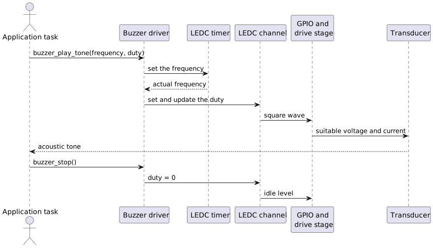
The timer sets the frequency, the channel applies the duty cycle, and the electrical stage adapts the signal to the transducer. To produce silence, the driver sets the duty to zero.
Basic driver
#include <stdint.h>#include "driver/ledc.h"#include "esp_check.h"#include "esp_err.h"#include "esp_log.h"#define BUZZER_PWM_GPIO GPIO_NUM_18#define BUZZER_LEDC_MODE LEDC_LOW_SPEED_MODE#define BUZZER_LEDC_TIMER LEDC_TIMER_0#define BUZZER_LEDC_CHANNEL LEDC_CHANNEL_0#define BUZZER_DUTY_BITS 10#define BUZZER_INITIAL_HZ 1000static char const* TAG = "buzzer";static bool buzzer_initialized;static uint32_t buzzer_duty_from_per_mille(uint16_t duty_per_mille) { uint32_t const max_duty = (1U << BUZZER_DUTY_BITS) - 1U; if (duty_per_mille > 1000U) { duty_per_mille = 1000U; } return (max_duty * duty_per_mille) / 1000U;}esp_err_t buzzer_init(void) { ledc_timer_config_t const timer_config = { .speed_mode = BUZZER_LEDC_MODE, .duty_resolution = (ledc_timer_bit_t)BUZZER_DUTY_BITS, .timer_num = BUZZER_LEDC_TIMER, .freq_hz = BUZZER_INITIAL_HZ, .clk_cfg = LEDC_AUTO_CLK, .deconfigure = false, }; ESP_RETURN_ON_ERROR(ledc_timer_config(&timer_config), TAG, "Unable to configure the LEDC timer"); ledc_channel_config_t const channel_config = { .gpio_num = BUZZER_PWM_GPIO, .speed_mode = BUZZER_LEDC_MODE, .channel = BUZZER_LEDC_CHANNEL, .intr_type = LEDC_INTR_DISABLE, .timer_sel = BUZZER_LEDC_TIMER, .duty = 0, .hpoint = 0, .sleep_mode = LEDC_SLEEP_MODE_NO_ALIVE_NO_PD, .flags = { .output_invert = 0, }, }; ESP_RETURN_ON_ERROR( ledc_channel_config(&channel_config), TAG, "Unable to configure the LEDC channel" ); buzzer_initialized = true; return ESP_OK;}esp_err_t buzzer_stop(void) { if (!buzzer_initialized) { return ESP_ERR_INVALID_STATE; } ESP_RETURN_ON_ERROR( ledc_set_duty(BUZZER_LEDC_MODE, BUZZER_LEDC_CHANNEL, 0), TAG, "Unable to clear the duty cycle" ); return ledc_update_duty(BUZZER_LEDC_MODE, BUZZER_LEDC_CHANNEL);}esp_err_t buzzer_play_tone(uint32_t frequency_hz, uint16_t duty_per_mille) { if (!buzzer_initialized) { return ESP_ERR_INVALID_STATE; } if (frequency_hz == 0 || duty_per_mille == 0) { return buzzer_stop(); } uint32_t const actual_hz = ledc_set_freq(BUZZER_LEDC_MODE, BUZZER_LEDC_TIMER, frequency_hz); if (actual_hz == 0) { ESP_LOGE(TAG, "Frequency %" PRIu32 " Hz cannot be configured", frequency_hz); return ESP_FAIL; } uint32_t const duty = buzzer_duty_from_per_mille(duty_per_mille); ESP_RETURN_ON_ERROR( ledc_set_duty(BUZZER_LEDC_MODE, BUZZER_LEDC_CHANNEL, duty), TAG, "Unable to set the duty cycle" ); ESP_RETURN_ON_ERROR( ledc_update_duty(BUZZER_LEDC_MODE, BUZZER_LEDC_CHANNEL), TAG, "Unable to update the duty cycle" ); ESP_LOGD( TAG, "Requested tone=%" PRIu32 " Hz, actual=%" PRIu32 " Hz, duty=%u/1000", frequency_hz, actual_hz, duty_per_mille ); return ESP_OK;}The file also requires:
#include <inttypes.h>#include <stdbool.h>In the component CMakeLists.txt:
idf_component_register( SRCS "buzzer.c" INCLUDE_DIRS "." PRIV_REQUIRES esp_driver_ledc)The operating sequence is:
buzzer_init() | +--> configures the LEDC timer +--> connects the channel to the GPIO +--> starts with duty 0buzzer_play_tone(440, 500) | +--> sets 440 Hz +--> sets a 50% duty cycle +--> the transducer emits the tonebuzzer_stop() | +--> sets duty to zero +--> the GPIO stops switching the loadWhy use zero duty for silence?
LEDC also exposes ledc_stop(), which suspends channel generation. (Espressif Systems)
In a small driver, it may be simpler to keep the channel configured and set the duty to zero. The next note then requires only:
- changing the frequency;
- restoring the duty cycle.
ledc_stop() remains useful when the output must be explicitly disabled or the idle level must be controlled. The choice depends on the driver architecture and on the required behavior during sleep and reconfiguration.
Frequency and duty-cycle resolution
LEDC must derive frequency and duty cycle from a source clock.
As the requested frequency increases, the available duty-cycle resolution may decrease. Espressif explicitly documents this tradeoff and returns an error when a combination cannot be implemented. (Espressif Systems)
A musical buzzer normally does not require very high duty-cycle resolution.
With 10 bits, we have:
2^10 = 1024 levelsA 50% duty cycle corresponds approximately to:
1024 / 2 = 512Even 8 bits would often be sufficient. The important requirement is that every frequency used by the melody can be generated with an acceptable error.
The value returned by ledc_set_freq() is the frequency that was actually configured. Logging it during development helps us understand whether the hardware is approximating the requested note.
Duty cycle is not a volume knob
Reducing duty cycle to lower the volume is common.
Does it always work?
Not quite.
Changing the duty cycle of a square wave simultaneously changes:
- average energy;
- the DC component of a unipolar signal;
- harmonic content;
- pulse duration;
- peak current;
- driver response;
- perceived timbre.
With a symmetrically driven piezoelectric transducer, 50% produces a balanced waveform and often excites the fundamental efficiently. Same Sky identifies 50% as a typical compromise between loudness and distortion, but the actual result depends on the component and circuit. (Same Sky)
Reducing the duty cycle may reduce the sound, but it is not equivalent to linearly reducing the amplitude of a sine wave.
For genuine intensity control, we may instead consider:
- driver supply voltage;
- differential drive;
- an attenuator or amplifier;
- high-frequency filtered PWM, if the transducer and circuit allow it;
- an amplitude envelope produced by dedicated audio hardware.
For simple beeps, three duty levels may be enough. For an expressive melody, a buzzer remains a limited instrument.
From frequency to musical notes
A melody is not normally described as a random list of frequencies.
It is more convenient to represent notes with an index and convert them when they are played.
The MIDI system assigns numbers from 0 to 127 to musical notes. In the common twelve-tone equal temperament, number 69 corresponds to A at 440 Hz. Frequency can be calculated with:
f(n) = 440 * 2^((n - 69) / 12)The formula and the 69 -> 440 Hz mapping are also documented by McGill University's Computational Acoustic Modeling Laboratory. MIDI.org likewise uses A4 = 440 Hz as its reference, while noting that octave-numbering conventions may vary. (McGill University) (MIDI Association)
Some common notes
| Note | MIDI number | Approximate frequency |
|---|---|---|
| C4 | 60 | 261.63 Hz |
| D4 | 62 | 293.66 Hz |
| E4 | 64 | 329.63 Hz |
| F4 | 65 | 349.23 Hz |
| G4 | 67 | 392.00 Hz |
| A4 | 69 | 440.00 Hz |
| B4 | 71 | 493.88 Hz |
| C5 | 72 | 523.25 Hz |
Octave names are not entirely consistent across software and manufacturers. The MIDI number removes that ambiguity: 60 always identifies the same pitch index, even if one interface displays it as C3 and another as C4.
Conversion in firmware
#include <math.h>#include <stdint.h>uint32_t buzzer_midi_to_frequency(uint8_t midi_note) { double const semitones = ((int)midi_note - 69) / 12.0; double const frequency = 440.0 * pow(2.0, semitones); if (frequency < 1.0) { return 1; } return (uint32_t)lround(frequency);}The result is rounded to the nearest whole hertz because ledc_set_freq() uses an integer frequency.
The introduced error is negligible for a common buzzer, whose mechanical tolerance and frequency response are normally far less precise than those of a musical synthesizer.
Avoiding calculations during playback
pow() is convenient and clear, but every note does not need to be calculated at runtime.
We can use a precomputed lookup table:
static uint16_t const note_frequency_hz[] = { [60] = 262, [61] = 277, [62] = 294, [63] = 311, [64] = 330, [65] = 349, [66] = 370, [67] = 392, [68] = 415, [69] = 440, [70] = 466, [71] = 494, [72] = 523,};Or generate the table during the build.
The choice depends on:
- required note range;
- floating-point usage;
- Flash size;
- readability;
- the need for different tunings.
Musical tempo and note duration
Tempo is often expressed in BPM, or beats per minute.
Assuming that one beat corresponds to a quarter note, the duration of a beat is:
beat_duration_ms = 60000 / BPMAt 120 BPM:
beat_duration_ms = 60000 / 120 = 500 msCommon note values become:
| Note value | Beats | Duration at 120 BPM |
|---|---|---|
| Whole note | 4 | 2000 ms |
| Half note | 2 | 1000 ms |
| Quarter note | 1 | 500 ms |
| Eighth note | 1/2 | 250 ms |
| Sixteenth note | 1/4 | 125 ms |
Dotted notes
A dot adds half of the note's original value:
dotted note = duration * 1.5A dotted quarter note at 120 BPM lasts:
500 ms * 1.5 = 750 msTriplets
Three notes normally occupy the space of two notes of the same value:
triplet duration = normal duration * 2 / 3Using milliseconds with fractions may introduce rounding. This is why sequencers commonly represent durations with an integer number of ticks.
Representing a melody with ticks
Let us define 96 ticks per quarter note:
#define BUZZER_TICKS_PER_QUARTER 96U#define DUR_SIXTEENTH (BUZZER_TICKS_PER_QUARTER / 4U)#define DUR_EIGHTH (BUZZER_TICKS_PER_QUARTER / 2U)#define DUR_QUARTER (BUZZER_TICKS_PER_QUARTER)#define DUR_HALF (BUZZER_TICKS_PER_QUARTER * 2U)#define DUR_WHOLE (BUZZER_TICKS_PER_QUARTER * 4U)The value 96 is divisible by 2, 3, 4, 6, 8, and 12. It therefore represents eighth notes, sixteenth notes, triplets, and dotted notes conveniently.
#define DUR_DOTTED_QUARTER (DUR_QUARTER + DUR_EIGHTH)#define DUR_EIGHTH_TRIPLET (BUZZER_TICKS_PER_QUARTER / 3U)The duration in milliseconds becomes:
duration_ms = 60000 * ticks / (BPM * ticks_per_quarter)In C, it is better to use a 64-bit integer to avoid overflow during multiplication:
uint32_t buzzer_ticks_to_ms(uint32_t ticks, uint16_t bpm) { if (bpm == 0) { return 0; } uint64_t const numerator = 60000ULL * ticks; uint64_t const denominator = (uint64_t)bpm * BUZZER_TICKS_PER_QUARTER; return (uint32_t)((numerator + denominator / 2U) / denominator);}Adding half the denominator rounds to the nearest value instead of simply truncating.
Notes, rests, and articulation
A melody is not made only of frequency and duration.
Two consecutive notes played without interruption may blend together, especially when they have the same frequency. A brief silence is required to separate them.
Let us therefore define a note as:
#define BUZZER_REST 0xFFUtypedef struct { uint8_t midi_note; uint16_t duration_ticks; uint8_t gate_percent;} buzzer_note_t;The fields mean:
midi_note: note pitch;duration_ticks: total time allocated to the event;gate_percent: percentage of that duration during which the tone remains active.
With gate_percent = 90:
90% -> sound10% -> silenceThis creates a slightly detached articulation.
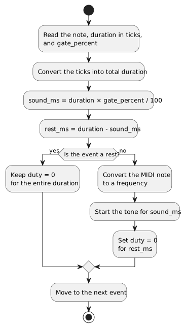
The gate divides the note's time slot into a sounding portion and a final rest. An explicit rest follows the same flow, but keeps the duty at zero for the entire duration.
With 100, notes are connected, but two identical consecutive notes will have no separating edge.
A rest uses:
{ .midi_note = BUZZER_REST, .duration_ticks = DUR_QUARTER, .gate_percent = 0, }A first original melody
Let us define a few pitches using MIDI numbers:
enum { NOTE_C4 = 60, NOTE_D4 = 62, NOTE_E4 = 64, NOTE_F4 = 65, NOTE_G4 = 67, NOTE_A4 = 69, NOTE_B4 = 71, NOTE_C5 = 72,};A small original melody can be represented as follows:
static buzzer_note_t const startup_melody[] = { {NOTE_C4, DUR_EIGHTH, 88}, {NOTE_E4, DUR_EIGHTH, 88}, {NOTE_G4, DUR_EIGHTH, 88}, {NOTE_C5, DUR_QUARTER, 92}, {NOTE_G4, DUR_EIGHTH, 88}, {NOTE_E4, DUR_EIGHTH, 88}, {NOTE_D4, DUR_QUARTER, 92}, {BUZZER_REST, DUR_EIGHTH, 0}, {NOTE_F4, DUR_EIGHTH, 88}, {NOTE_A4, DUR_EIGHTH, 88}, {NOTE_C5, DUR_QUARTER, 92}, {NOTE_A4, DUR_EIGHTH, 88}, {NOTE_G4, DUR_EIGHTH, 88}, {NOTE_E4, DUR_EIGHTH, 88}, {NOTE_C4, DUR_HALF, 96},};The sequence rises through a C-major chord, returns toward the middle, introduces a second phrase, and closes on the tonic.
We do not need to know all of harmony to begin. It is enough to understand that an effective buzzer melody should:
- use a frequency range in which the transducer is audible;
- avoid notes that are too short for the system;
- alternate tension and resolution;
- leave recognizable rests;
- avoid too many extreme jumps.
A blocking but temporally stable player
A first implementation can live in a dedicated task and use xTaskDelayUntil().
Unlike vTaskDelay(), which delays relative to the moment it is called, xTaskDelayUntil() uses an absolute deadline relative to an updated reference. This reduces accumulated drift. In ESP-IDF 6.0, the old deprecated vTaskDelayUntil() function was removed and xTaskDelayUntil() must be used instead. (Espressif Systems)
#include "freertos/FreeRTOS.h"#include "freertos/task.h"esp_err_tbuzzer_play_sequence_blocking(buzzer_note_t const* notes, size_t note_count, uint16_t bpm) { if (notes == NULL || note_count == 0 || bpm == 0) { return ESP_ERR_INVALID_ARG; } TickType_t wake_time = xTaskGetTickCount(); for (size_t i = 0; i < note_count; ++i) { buzzer_note_t const* note = ¬es[i]; uint32_t const total_ms = buzzer_ticks_to_ms(note->duration_ticks, bpm); uint32_t sound_ms = 0; if (note->midi_note != BUZZER_REST) { sound_ms = (total_ms * note->gate_percent) / 100U; } if (sound_ms > total_ms) { sound_ms = total_ms; } uint32_t const silence_ms = total_ms - sound_ms; if (sound_ms > 0) { uint32_t const frequency_hz = buzzer_midi_to_frequency(note->midi_note); ESP_RETURN_ON_ERROR( buzzer_play_tone(frequency_hz, 500), TAG, "Unable to play note %u", note->midi_note ); xTaskDelayUntil(&wake_time, pdMS_TO_TICKS(sound_ms)); } ESP_RETURN_ON_ERROR(buzzer_stop(), TAG, "Unable to stop the buzzer"); if (silence_ms > 0) { xTaskDelayUntil(&wake_time, pdMS_TO_TICKS(silence_ms)); } } return buzzer_stop();}Usage:
ESP_ERROR_CHECK(buzzer_play_sequence_blocking( startup_melody, sizeof(startup_melody) / sizeof(startup_melody[0]), 132));Limit of conversion to FreeRTOS ticks
pdMS_TO_TICKS() converts milliseconds to the granularity of the operating-system tick.
A very short duration may become zero ticks. To prevent notes from disappearing, we should enforce at least one tick whenever the requested duration is greater than zero:
static TickType_t buzzer_ms_to_os_ticks(uint32_t duration_ms) { if (duration_ms == 0) { return 0; } TickType_t ticks = pdMS_TO_TICKS(duration_ms); if (ticks == 0) { ticks = 1; } return ticks;}Then replace pdMS_TO_TICKS() with this function.
The limitation does not disappear: a duration shorter than one tick is rounded. If more precise events are required, we can use esp_timer or GPTimer to schedule note changes while still leaving the audio carrier generation to LEDC.
Understanding what happens during playback
Let us add a log entry for each event:
ESP_LOGI( TAG, "index=%u note=%u freq=%" PRIu32 "Hz total=%" PRIu32 "ms sound=%" PRIu32 "ms rest=%" PRIu32 "ms", (unsigned)i, note->midi_note, frequency_hz, total_ms, sound_ms, silence_ms);A possible output is:
I buzzer: index=0 note=60 freq=262Hz total=227ms sound=199ms rest=28msI buzzer: index=1 note=64 freq=330Hz total=227ms sound=199ms rest=28msI buzzer: index=2 note=67 freq=392Hz total=227ms sound=199ms rest=28msI buzzer: index=3 note=72 freq=523Hz total=455ms sound=418ms rest=37msFrom the peripheral point of view:
note C4 | +--> MIDI 60 +--> converted to 262 Hz +--> LEDC changes the timer to roughly 262 Hz +--> duty goes from 0 to 50% +--> the transistor switches the transducer +--> the diaphragm vibrates +--> after the gate time, duty returns to 0 +--> articulation rest +--> next noteThis separation helps diagnose problems.
If the log shows the correct frequency but the sound does not change, possible causes include:
- an active buzzer instead of a passive one;
- a module that filters PWM;
- a transistor that is too slow;
- a component used outside its useful frequency range;
- a frequency shared with another LEDC channel;
- incorrect wiring.
Why a player should not block the application
The previous function blocks the calling task until the melody ends.
In real firmware, we may want to:
- accept a new notification while a sound is playing;
- interrupt a confirmation tone to play an alarm;
- stop the buzzer immediately;
- change volume or tempo;
- prevent the UI from waiting for the sequence to end;
- serialize requests coming from different tasks.
The simplest solution is to dedicate one task to the buzzer and communicate with it through a queue.
UI task --------+network task ---+--> command queue --> buzzer task --> LEDCsensor task ----+This way, only the buzzer task modifies the peripheral.
Commands and priorities
Let us define a sequence:
typedef struct { buzzer_note_t const* notes; size_t note_count; uint16_t bpm; uint8_t priority; bool loop;} buzzer_sequence_t;And the commands:
typedef enum { BUZZER_COMMAND_PLAY, BUZZER_COMMAND_STOP,} buzzer_command_type_t;typedef struct { buzzer_command_type_t type; buzzer_sequence_t sequence;} buzzer_command_t;The memory referenced by notes must remain valid for the entire playback. static const sequences meet this requirement. Passing a local array created on the stack and then returning from the function would instead leave an invalid pointer.
Priority policy
One possible policy is:
priority 0 -> UI feedbackpriority 1 -> notificationpriority 2 -> errorpriority 3 -> alarmWhen a new request arrives:
- if it has lower priority, it may be ignored or queued;
- if it has equal priority, it may replace the current one;
- if it has higher priority, it interrupts the current sound;
STOPalways interrupts.
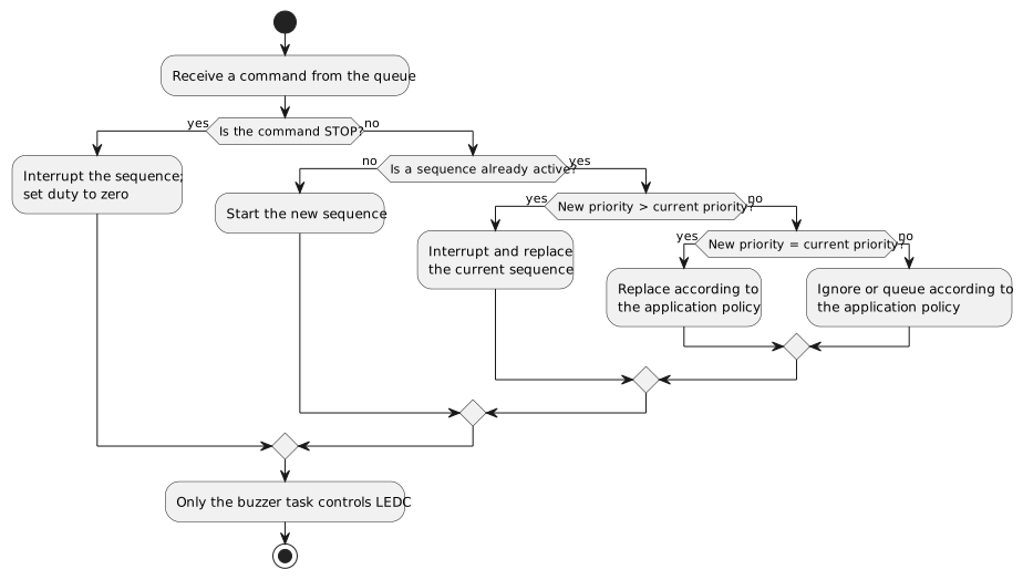
The queue serializes commands and a single task owns LEDC. Higher-priority requests may interrupt the current sequence, while equal- and lower-priority behavior remains an explicit application policy.
There is no universal policy. The important point is to make it explicit instead of letting whichever task last calls LEDC win by accident.
Non-blocking player with a queue
The following example keeps the logic readable and checks the queue both during the sound and during the rest.
#include <stdbool.h>#include <stddef.h>#include <stdint.h>#include <string.h>#include "freertos/FreeRTOS.h"#include "freertos/queue.h"#include "freertos/task.h"#define BUZZER_QUEUE_LENGTH 6static QueueHandle_t buzzer_command_queue;static TaskHandle_t buzzer_task_handle;static bool buzzer_wait_for_command(TickType_t timeout, buzzer_command_t* command) { return xQueueReceive(buzzer_command_queue, command, timeout) == pdTRUE;}static boolbuzzer_should_preempt(buzzer_sequence_t const* current, buzzer_command_t const* incoming) { if (incoming->type == BUZZER_COMMAND_STOP) { return true; } return incoming->sequence.priority >= current->priority;}static bool buzzer_wait_interruptible( TickType_t duration, buzzer_sequence_t const* current, buzzer_command_t* replacement) { if (duration == 0) { return false; } TickType_t const start = xTaskGetTickCount(); TickType_t remaining = duration; while (remaining > 0) { buzzer_command_t incoming; if (!buzzer_wait_for_command(remaining, &incoming)) { return false; } if (buzzer_should_preempt(current, &incoming)) { *replacement = incoming; return true; } ESP_LOGD( TAG, "Command ignored: new priority=%u, current=%u", incoming.sequence.priority, current->priority ); TickType_t const elapsed = xTaskGetTickCount() - start; if (elapsed >= duration) { return false; } remaining = duration - elapsed; } return false;}static bool buzzer_play_one_note( buzzer_note_t const* note, uint16_t bpm, buzzer_sequence_t const* current, buzzer_command_t* replacement) { uint32_t const total_ms = buzzer_ticks_to_ms(note->duration_ticks, bpm); uint32_t sound_ms = 0; if (note->midi_note != BUZZER_REST) { sound_ms = (total_ms * note->gate_percent) / 100U; } if (sound_ms > total_ms) { sound_ms = total_ms; } uint32_t const rest_ms = total_ms - sound_ms; if (sound_ms > 0) { uint32_t const frequency_hz = buzzer_midi_to_frequency(note->midi_note); if (buzzer_play_tone(frequency_hz, 500) != ESP_OK) { ESP_LOGE(TAG, "Error while starting the note"); buzzer_stop(); return false; } if (buzzer_wait_interruptible(buzzer_ms_to_os_ticks(sound_ms), current, replacement)) { buzzer_stop(); return true; } } buzzer_stop(); if ( rest_ms > 0 && buzzer_wait_interruptible(buzzer_ms_to_os_ticks(rest_ms), current, replacement) ) { return true; } return false;}static void buzzer_task(void* argument) { (void)argument; buzzer_command_t command; while (true) { if (xQueueReceive(buzzer_command_queue, &command, portMAX_DELAY) != pdTRUE) { continue; } if (command.type == BUZZER_COMMAND_STOP) { buzzer_stop(); continue; } buzzer_sequence_t current = command.sequence; size_t index = 0; while (true) { if (current.notes == NULL || current.note_count == 0 || current.bpm == 0) { buzzer_stop(); break; } buzzer_command_t replacement; bool const interrupted = buzzer_play_one_note(¤t.notes[index], current.bpm, ¤t, &replacement); if (interrupted) { if (replacement.type == BUZZER_COMMAND_STOP) { buzzer_stop(); break; } current = replacement.sequence; index = 0; continue; } ++index; if (index >= current.note_count) { if (current.loop) { index = 0; } else { buzzer_stop(); break; } } } }}Initialization:
esp_err_t buzzer_player_init(void) { ESP_RETURN_ON_ERROR(buzzer_init(), TAG, "Unable to initialize LEDC"); buzzer_command_queue = xQueueCreate(BUZZER_QUEUE_LENGTH, sizeof(buzzer_command_t)); if (buzzer_command_queue == NULL) { return ESP_ERR_NO_MEM; } BaseType_t const created = xTaskCreate(buzzer_task, "buzzer", 4096, NULL, 5, &buzzer_task_handle); if (created != pdPASS) { vQueueDelete(buzzer_command_queue); buzzer_command_queue = NULL; return ESP_ERR_NO_MEM; } return ESP_OK;}Sending a sequence:
esp_err_t buzzer_player_play(buzzer_sequence_t const* sequence, TickType_t timeout) { if ( sequence == NULL || sequence->notes == NULL || sequence->note_count == 0 || sequence->bpm == 0 || buzzer_command_queue == NULL ) { return ESP_ERR_INVALID_ARG; } buzzer_command_t const command = { .type = BUZZER_COMMAND_PLAY, .sequence = *sequence, }; return xQueueSend(buzzer_command_queue, &command, timeout) == pdTRUE ? ESP_OK : ESP_ERR_TIMEOUT;}Stopping:
esp_err_t buzzer_player_stop(TickType_t timeout) { if (buzzer_command_queue == NULL) { return ESP_ERR_INVALID_STATE; } buzzer_command_t const command = { .type = BUZZER_COMMAND_STOP, }; return xQueueSendToFront(buzzer_command_queue, &command, timeout) == pdTRUE ? ESP_OK : ESP_ERR_TIMEOUT;}A limitation of the example queue
The task checks for new commands only within the boundaries of two intervals:
- the audible part;
- the silent part.
If a note lasts two seconds, a command can still interrupt it because xQueueReceive() waits with a timeout for the entire audible duration.
However, a lower-priority command is consumed and ignored. In a system that must not lose notifications, a more elaborate policy is required:
- separate queues for different priorities;
- a priority queue;
- reinserting the command;
- an event scheduler;
- storage for pending notifications.
The example shows the fundamental logic; it does not claim to be a universal sequencer.
Using esp_timer for musical events
When the precision of the FreeRTOS tick is not sufficient, we can schedule the end of a note with a one-shot timer.
The callback should not perform long processing. It can instead notify the buzzer task:
#include "esp_timer.h"static TaskHandle_t precise_buzzer_task_handle;static void buzzer_timer_callback(void* argument) { (void)argument; xTaskNotifyGive(precise_buzzer_task_handle);}Configuration:
static esp_timer_handle_t buzzer_event_timer;esp_err_t buzzer_event_timer_init(void) { esp_timer_create_args_t const args = { .callback = buzzer_timer_callback, .arg = NULL, .dispatch_method = ESP_TIMER_TASK, .name = "buzzer_event", .skip_unhandled_events = true, }; return esp_timer_create(&args, &buzzer_event_timer);}Inside the task:
ESP_ERROR_CHECK(buzzer_play_tone(frequency_hz, 500));ESP_ERROR_CHECK(esp_timer_start_once(buzzer_event_timer, sound_duration_us));ulTaskNotifyTake(pdTRUE, portMAX_DELAY);ESP_ERROR_CHECK(buzzer_stop());Espressif recommends short callbacks because task-dispatch callbacks are executed serially inside the esp_timer task. It points to GPTimer as an alternative when more real-time timing is required. (Espressif Systems) (Espressif Systems)
For a normal melody, millisecond resolution is generally sufficient. esp_timer becomes interesting when:
- the tempo is high;
- notes are very short;
- sounds and animations must be synchronized;
- the FreeRTOS tick is too coarse;
- accumulated drift must be reduced without busy waiting.
Frequency sweep
A sweep changes frequency gradually.
It is useful for:
- startup effects;
- confirmations;
- alarms;
- finding the resonant frequency;
- testing the transducer and enclosure.
esp_err_tbuzzer_sweep_blocking(uint32_t start_hz, uint32_t end_hz, uint32_t step_hz, uint32_t step_ms) { if (start_hz == 0 || end_hz == 0 || step_hz == 0 || step_ms == 0) { return ESP_ERR_INVALID_ARG; } if (start_hz <= end_hz) { for (uint32_t hz = start_hz; hz <= end_hz;) { ESP_RETURN_ON_ERROR(buzzer_play_tone(hz, 500), TAG, "Sweep error at %" PRIu32 " Hz", hz); vTaskDelay(pdMS_TO_TICKS(step_ms)); if (end_hz - hz < step_hz) { break; } hz += step_hz; } } else { for (uint32_t hz = start_hz; hz >= end_hz;) { ESP_RETURN_ON_ERROR(buzzer_play_tone(hz, 500), TAG, "Sweep error at %" PRIu32 " Hz", hz); vTaskDelay(pdMS_TO_TICKS(step_ms)); if (hz - end_hz < step_hz) { break; } hz -= step_hz; } } return buzzer_stop();}Example:
ESP_ERROR_CHECK(buzzer_sweep_blocking(500, 4000, 50, 10));During the test, loudness may rise sharply near resonance.
Logging frequency together with a microphone or SPL measurement lets us build an approximate response curve for the assembled system.
Musical glissando
A linear sweep in hertz does not correspond to a linear movement in semitones.
Musical perception is logarithmic. To move from one MIDI note to another in uniform pitch steps, we can interpolate the note number and convert it to frequency:
esp_err_tbuzzer_glissando_blocking(uint8_t start_note, uint8_t end_note, uint16_t total_ms, uint16_t steps) { if (steps == 0 || total_ms == 0) { return ESP_ERR_INVALID_ARG; } int const start = start_note; int const distance = (int)end_note - start; uint32_t const step_ms = total_ms / steps; for (uint16_t i = 0; i <= steps; ++i) { double const position = (double)i / steps; double const midi = start + distance * position; double const frequency = 440.0 * pow(2.0, (midi - 69.0) / 12.0); ESP_RETURN_ON_ERROR( buzzer_play_tone((uint32_t)lround(frequency), 500), TAG, "Error during glissando" ); vTaskDelay(pdMS_TO_TICKS(step_ms)); } return buzzer_stop();}The result depends on how quickly LEDC changes frequency and on the response of the transducer.
With only a few steps, we hear a discrete scale. With many steps, the transition becomes more continuous, but the number of reconfigurations increases.
Arpeggios and chords
A single PWM channel generates one fundamental frequency at a time.
Consequently, one passive buzzer is naturally monophonic.
A chord requires multiple simultaneous frequencies. We can work around the limitation with an arpeggio:
C4 -> E4 -> G4 -> C5The notes are played rapidly one after another, and the brain perceives a harmonic structure even though it is not a true chord.
static buzzer_note_t const major_arpeggio[] = { {NOTE_C4, DUR_SIXTEENTH, 85}, {NOTE_E4, DUR_SIXTEENTH, 85}, {NOTE_G4, DUR_SIXTEENTH, 85}, {NOTE_C5, DUR_SIXTEENTH, 85},};It is possible to alternate two frequencies rapidly or generate a software waveform that sums several frequencies, but the result:
- requires a much higher update rate;
- produces aliasing and harmonics;
- is no longer a simple LEDC use case;
- depends heavily on the transducer;
- remains far from the quality of a loudspeaker.
If polyphony is a real requirement, it is better to change the architecture.
Designing acoustic signals before melodies
In an embedded product, music is not always the primary goal.
We often need to build an acoustic language.
A good signal should be:
- recognizable;
- short;
- consistent;
- unambiguous;
- proportional to the severity of the event;
- distinguishable from environmental noise;
- not excessively annoying.
One possible grammar is:
| Event | Pattern |
|---|---|
| Valid press | short mid-high tone |
| Operation completed | two ascending notes |
| Operation canceled | two descending notes |
| Recoverable error | three medium pulses |
| Critical error | repeated alternation between two frequencies |
| Low battery | short pulse repeated at long intervals |
| Startup | ascending arpeggio |
| Shutdown | descending arpeggio |
Meaning should remain consistent throughout the product.
Using the same sequence for “operation successful” and “error” makes the feedback useless, even when the melody is technically correct.
Building a readable melody
When composing a short buzzer melody, it helps to work in layers.
1. Choose a useful range
Before writing notes, run a sweep and identify the region in which the buzzer is sufficiently audible.
Suppose the component works well between 600 Hz and 2500 Hz.
A C4 at roughly 262 Hz may sound weak. We could therefore transpose the melody up one octave:
C4 -> C5E4 -> E5G4 -> G5One octave doubles frequency:
f_octave = 2 * fTransposition does not change the musical relationships, but it may adapt the sequence to the transducer.
2. Define the rhythm
A recognizable melody needs temporal structure.
We can begin with a simple cell:
eighth note, eighth note, quarter noteRepeating it with different pitches creates coherence.
3. Use real rests
A rest is not wasted time.
It helps to:
- separate phrases;
- distinguish repeated pitches;
- reduce listener fatigue;
- create expectation;
- encode meaning.
4. Limit the duration
UI feedback should normally be brief.
A startup melody may be longer, but it should not prevent interaction or mask more important alarms.
5. Test on the real device
The same sequence may sound pleasant on a loudspeaker and unpleasant on a resonant piezo device.
We need to listen to it:
- inside the enclosure;
- at the actual supply voltage;
- with the real power system;
- while Wi-Fi and other loads are active;
- at different temperatures, when relevant;
- from the expected use distance.
Useful scales for getting started
A major scale contains seven notes before the octave.
For C major:
C D E F G A B CMIDI numbers:
static uint8_t const c_major_scale[] = {60, 62, 64, 65, 67, 69, 71, 72};A major pentatonic scale uses five notes:
C D E G Astatic uint8_t const c_major_pentatonic[] = {60, 62, 64, 67, 69, 72};The pentatonic scale is useful for small effects because it reduces the likelihood of strongly dissonant combinations.
An A natural minor scale is:
A B C D E F G Astatic uint8_t const a_natural_minor[] = {69, 71, 72, 74, 76, 77, 79, 81};These structures do not force us to write tonal music. They simply provide an initial set of frequencies with predictable relationships.
Generating a melody from scale degrees
Separating a melody from its key makes transposition easy.
typedef struct { int8_t degree; int8_t octave_offset; uint16_t duration_ticks; uint8_t gate_percent;} scale_event_t;With a seven-note scale:
uint8_tscale_degree_to_midi(uint8_t const* scale, size_t scale_size, int degree, int octave_offset) { int octave = octave_offset; while (degree < 0) { degree += (int)scale_size; --octave; } while (degree >= (int)scale_size) { degree -= (int)scale_size; ++octave; } return (uint8_t)(scale[degree] + octave * 12);}A phrase can be described as:
static scale_event_t const phrase[] = { {.degree = 0, .octave_offset = 0, .duration_ticks = DUR_EIGHTH, .gate_percent = 88}, {.degree = 2, .octave_offset = 0, .duration_ticks = DUR_EIGHTH, .gate_percent = 88}, {.degree = 4, .octave_offset = 0, .duration_ticks = DUR_QUARTER, .gate_percent = 92}, {.degree = 0, .octave_offset = 1, .duration_ticks = DUR_HALF, .gate_percent = 95},};Using a major scale produces a major phrase. Using a minor scale with the same scale-degree pattern produces a different character.
This representation is useful when firmware generates procedural variations or must adapt the key to a user profile.
Articulation and envelope
A buzzer driven by a simple square wave moves instantly from silence to full excitation.
A classic musical envelope is often described as:
Attack -> Decay -> Sustain -> ReleaseWith LEDC, we can attempt an approximation by changing the duty cycle over time.
However, as discussed earlier, duty cycle and amplitude are not equivalent. The resulting effect changes timbre as well.
A simple version:
static esp_err_t buzzer_attack( uint32_t frequency_hz, uint16_t start_duty, uint16_t end_duty, uint16_t steps, uint16_t step_ms) { if (steps == 0) { return ESP_ERR_INVALID_ARG; } for (uint16_t i = 0; i <= steps; ++i) { uint32_t const duty = start_duty + ((uint32_t)(end_duty - start_duty) * i) / steps; ESP_RETURN_ON_ERROR(buzzer_play_tone(frequency_hz, (uint16_t)duty), TAG, "Error during attack"); vTaskDelay(pdMS_TO_TICKS(step_ms)); } return ESP_OK;}This code assumes end_duty >= start_duty. A reusable driver should also handle a downward ramp without underflow.
LEDC also includes a hardware fade engine that changes duty cycle gradually without continuous CPU intervention. The peripheral was designed for LEDs, but the same feature can be experimented with for rudimentary envelopes, keeping in mind that the acoustic result depends on the circuit. (Espressif Systems)
Frequency sharing between LEDC channels
LEDC channels are connected to timers.
Frequency belongs to the timer, not only to the channel.
If the buzzer shares LEDC_TIMER_0 with an LED or another PWM output, calling ledc_set_freq() changes the timer and may therefore affect every channel connected to it.
It is consequently better to reserve for the buzzer:
- a dedicated LEDC timer;
- a dedicated channel;
- a GPIO supported by the target.
The LEDC architecture and the relationship between timers and channels are described in the Espressif documentation. (Espressif Systems)
The problem is easy to recognize:
the buzzer changes note | +--> at the same time, an LED changes behaviorThe cause is not FreeRTOS. It is the shared PWM timer.
Sleep and output behavior
LEDC lets us configure channel behavior during Light-sleep through sleep_mode. Actual support depends on the target and selected clock. The default mode does not necessarily keep the signal running while the device sleeps. (Espressif Systems)
Before entering sleep, we need to decide:
- should the buzzer stop?
- must an alarm continue?
- should the sound wake the system?
- does the timer retain its frequency?
- does the GPIO move to a safe level?
- does the transistor remain off?
For most interfaces, I prefer to:
- send
STOPto the player; - wait until the output is disabled;
- put the pin in a safe state;
- enter sleep.
An alarm that must remain active while the CPU sleeps instead requires target-specific analysis of the clock and power domains.
When to use PWM Audio
Espressif provides a PWM Audio component that uses LEDC to produce PWM audio without an external codec. It is intended for cost-sensitive applications with modest quality requirements; it supports sample rates from 8 to 48 kHz and PWM resolutions from 8 to 10 bits. (Espressif Systems)
This approach is different from a simple tone:
note-based melody -> LEDC changes frequency for each notePWM Audio -> a sample stream changes duty rapidly -> a filter / transducer reconstructs the average signalPWM Audio becomes interesting when we want:
- sampled sound effects;
- waveforms other than a square wave;
- short, low-quality voice clips;
- more complex synthesis.
However, it requires:
- more memory bandwidth;
- more CPU or DMA, depending on the implementation;
- filtering;
- suitable amplification;
- a transducer with sufficient bandwidth.
A resonant buzzer remains a poor loudspeaker. Even with perfect samples, the component may emphasize a narrow frequency region and make speech unintelligible.
When to move to I2S and a loudspeaker
If the requirements include:
- intelligible speech;
- music;
- polyphony;
- WAV or MP3 files;
- genuine volume control;
- wider frequency response;
- repeatable quality;
it is better to use a loudspeaker with an amplifier and, when needed, a codec or DAC.
ESP32 provides I2S peripherals for transferring digital audio samples. Espressif describes I2S as a synchronous bus for communication between digital audio devices. (Espressif Systems)
In essence:
buzzer -> signals and simple melodiesspeaker -> audioTrying to turn an inexpensive buzzer into a complete audio system increases firmware complexity without overcoming the mechanical limits of the component.
Common mistakes
Using an active buzzer for a melody
The internal frequency remains dominant. External PWM can only interrupt the tone and create rhythmic modulation.
Connecting a magnetic transducer directly to the GPIO
The current may exceed what the pin can safely supply, and the coil may generate an overvoltage when switched off.
Adding the wrong diode to a piezo device
A piezo is not a coil. The circuit must be selected according to its electrical model and the manufacturer's recommendations.
Ignoring Vp-p
3 V0-p, 3 Vrms, and 3 Vp-p describe different excitations. Direct comparison between datasheets then becomes incorrect.
Assuming every note has the same loudness
The response of the buzzer and acoustic cavity varies with frequency. A melody may sound strongly unbalanced.
Treating duty cycle as linear volume
Duty cycle changes harmonic content and waveform as well. Perceived loudness does not necessarily follow a linear relationship.
Sharing the LEDC timer
Changing the buzzer note also changes other channels connected to the same timer.
Using vTaskDelay() throughout a long sequence
The time spent in calculations, logging, and scheduling is added to each relative delay and may introduce drift.
Heavy logging during short notes
Log serialization may alter timing and make debug and release builds behave differently.
Leaving the buzzer active after an error
An early return may skip buzzer_stop() and produce a permanent tone.
Every exit path should therefore return the hardware to a safe state.
Passing a local melody to the queue
The buzzer task receives a pointer to memory that no longer exists after the calling function returns.
Shared melodies must have a sufficient lifetime, for example static const.
Ignoring reset behavior
During boot, a GPIO may float or temporarily serve another function. A hardware pull-down on the transistor prevents unintended beeps before software initialization.
Diagnostics
Different tools reveal different buzzer problems.
Multimeter
It can verify:
- supply voltage;
- continuity;
- coil resistance;
- polarity;
- average GPIO state.
It does not display the PWM waveform correctly.
Oscilloscope
It can show:
- actual frequency;
- duty cycle;
- peak-to-peak voltage;
- overshoot;
- flyback behavior;
- rise and fall times;
- power-supply noise;
- push-pull synchronization.
Differential measurements across a bridge require particular care. Connecting the ground clip of a conventional probe to the wrong node may short the circuit through the instrument's earth connection.
Logic analyzer
It is useful for verifying:
- note sequence;
- pulse duration;
- intervals;
- jitter;
- the relationship between the buzzer and other digital events.
It does not correctly measure analog transients or voltages outside logic levels.
Microphone or sound-level meter
It allows us to compare:
- frequencies;
- different enclosures;
- different voltages;
- distances;
- orientation;
- individual samples.
A smartphone can help with comparative testing, but it is not automatically a substitute for a calibrated SPL measurement.
Firmware test logic
A useful test should not stop at “I can hear something.”
We can build a procedure that:
- initializes the driver;
- plays fixed frequencies;
- verifies the frequency with an oscilloscope;
- runs a sweep;
- identifies resonance;
- plays a scale;
- verifies total duration;
- sends an interruption command;
- enters and exits sleep;
- repeats the test with radio and other loads active.
Example test task:
static void buzzer_test_task(void* argument) { (void)argument; uint32_t const test_frequencies[] = { 500, 1000, 2000, 4000, }; for (size_t i = 0; i < sizeof(test_frequencies) / sizeof(test_frequencies[0]); ++i) { ESP_LOGI(TAG, "Tone test: %" PRIu32 " Hz", test_frequencies[i]); ESP_ERROR_CHECK(buzzer_play_tone(test_frequencies[i], 500)); vTaskDelay(pdMS_TO_TICKS(500)); ESP_ERROR_CHECK(buzzer_stop()); vTaskDelay(pdMS_TO_TICKS(250)); } ESP_ERROR_CHECK(buzzer_sweep_blocking(300, 5000, 50, 15)); ESP_ERROR_CHECK(buzzer_play_sequence_blocking( startup_melody, sizeof(startup_melody) / sizeof(startup_melody[0]), 132 )); vTaskDelete(NULL);}Measuring timing error
We can compare theoretical and real duration using esp_timer_get_time():
#include "esp_timer.h"int64_t const start_us = esp_timer_get_time();ESP_ERROR_CHECK(buzzer_play_sequence_blocking( startup_melody, sizeof(startup_melody) / sizeof(startup_melody[0]), 132));int64_t const elapsed_us = esp_timer_get_time() - start_us;ESP_LOGI(TAG, "Actual duration: %.3f s", elapsed_us / 1000000.0);The theoretical duration is the sum of the ticks:
uint64_t buzzer_sequence_duration_ms(buzzer_note_t const* notes, size_t note_count, uint16_t bpm) { uint64_t total_ticks = 0; for (size_t i = 0; i < note_count; ++i) { total_ticks += notes[i].duration_ticks; } return (60000ULL * total_ticks + ((uint64_t)bpm * BUZZER_TICKS_PER_QUARTER) / 2U) / ((uint64_t)bpm * BUZZER_TICKS_PER_QUARTER);}Differences of a few milliseconds may result from:
- rounding;
- tick granularity;
- scheduling;
- logging;
- LEDC reconfiguration.
If the error grows note after note, the problem is probably drift in the timing logic. If it remains almost constant, it may be initial or final overhead.
Separating the driver, sequencer, and meaning
A clean structure can be divided into three layers.
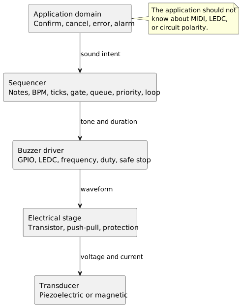
The domain requests a sound intent, the sequencer translates it into timed events, and the driver controls the peripheral. The electrical circuit and transducer remain details confined below that interface.
Driver
Responsible for:
- GPIO;
- LEDC;
- frequency;
- duty cycle;
- stopping;
- a safe electrical state.
Interface:
esp_err_t buzzer_init(void);esp_err_t buzzer_play_tone(uint32_t hz, uint16_t duty_per_mille);esp_err_t buzzer_stop(void);Sequencer
Responsible for:
- notes;
- BPM;
- ticks;
- gate time;
- queue;
- priorities;
- loops;
- interruptions.
Interface:
esp_err_t buzzer_player_play(buzzer_sequence_t const* sequence, TickType_t timeout);esp_err_t buzzer_player_stop(TickType_t timeout);Application domain
Responsible for meaning:
void ui_sound_confirm(void);void ui_sound_cancel(void);void system_sound_error(void);void system_sound_alarm(void);The application should not know MIDI numbers or LEDC channels.
Example:
void ui_sound_confirm(void) { static buzzer_sequence_t const sequence = { .notes = success_melody, .note_count = sizeof(success_melody) / sizeof(success_melody[0]), .bpm = 180, .priority = 0, .loop = false, }; esp_err_t const error = buzzer_player_play(&sequence, 0); if (error != ESP_OK) { ESP_LOGW(TAG, "Acoustic feedback was not queued"); }}This separation lets us change the hardware without rewriting the semantics of the interface.
Selection table
| Application | Component | Recommended drive |
|---|---|---|
| Confirmation click | active indicator | GPIO + transistor |
| Error pattern | active indicator | task + on/off sequence |
| Simple melody | passive transducer | LEDC + transistor/driver |
| Alarm sweep | passive transducer | LEDC + scheduler |
| High sound pressure | piezo + dedicated driver | bridge or manufacturer-recommended circuit |
| Magnetic buzzer | magnetic transducer | transistor + clamp |
| Low-cost sampled audio | loudspeaker or suitable transducer | PWM Audio + filter/amplifier |
| Speech or music | loudspeaker | I2S + DAC/codec/amplifier |
| Regulated alarm | qualified component | architecture compliant with the applicable standard |
Hardware checklist
Before finalizing the schematic, it is worth answering these questions:
- Is the component piezoelectric or magnetic?
- Is it an indicator or a transducer?
- Does it include an oscillator?
- What is the rated voltage?
- Is the value specified as
VDC,Vrms,V0-p, orVp-p? - What current does it require?
- What is the rated frequency?
- What are its capacitance or impedance?
- Is a transistor required?
- Is a flyback diode required?
- Is a discharge resistor required?
- Does the GPIO assume a safe state during reset?
- Must the buzzer remain active during sleep?
- Has the acoustic cavity been designed?
- Is the enclosure opening large enough?
- Is the component protected from water and dust?
- Is continuous duty permitted?
- Has the circuit been verified with an oscilloscope?
- Was the measurement performed at the actual operating voltage?
- Was the test repeated in the assembled product?
Firmware checklist
- Does the driver hide electrical polarity?
- Does LEDC use a dedicated timer?
- Is the actual frequency checked?
- Is stop executed even after an error?
- Do melody arrays have a sufficient lifetime?
- Do duration calculations use 64-bit integers?
- Are short notes rounded to at least one tick?
- Does the sequence accumulate drift?
- Does the player run in a dedicated task?
- Is there an explicit priority policy?
- Can an alarm interrupt UI feedback?
- Can stop interrupt a long note?
- Do logs alter timing?
- Is sleep behavior defined?
- Does the player handle reset or deinitialization?
- Does the firmware distinguish rests from notes?
- Are identical consecutive notes separated?
- Is duty cycle treated cautiously?
- Are the frequencies suitable for the actual component?
- Do sounds have consistent meaning throughout the interface?
Conclusion
My conclusion is that a buzzer is simple only as long as we consider it a component capable of producing any arbitrary noise.
As soon as we want recognizable and repeatable feedback, several layers come into play.
The physical technology determines how vibration is produced. The internal circuit determines whether DC power is sufficient or an external waveform is required. The drive stage must respect current, voltage, and the nature of the load. The enclosure modifies the acoustic response. LEDC generates the tone, while the sequencer gives events duration, rhythm, and priority. Finally, the application decides what that sound means.
Confusing these layers leads to the most common problems: using an active buzzer for a melody, driving a coil directly from a GPIO, interpreting duty cycle as linear volume, ignoring resonance, or blocking the whole application during a jingle.
In ESP-IDF, LEDC is a natural solution for passive transducers because it generates stable PWM in hardware and allows frequency changes at runtime. A dedicated task can then transform notes, BPM, rests, and priorities into a temporal sequence without distributing peripheral control throughout the firmware.
However, a buzzer remains a signaling device. It can reproduce simple melodies, sweeps, and surprisingly effective patterns, but it does not become a loudspeaker merely because the firmware generates more samples.
In essence, the best choice is not the longest sound or the most complex melody. It is the signal that the component can produce reliably and that the user can interpret without hesitation.
Main sources consulted
The distinction between piezoelectric and magnetic technology, between indicators and transducers, and the corresponding drive circuits was verified against the technical documentation from Same Sky and Murata. (Same Sky) (Murata) (Murata)
Frequency, voltage, and sound-pressure characteristics were compared with TDK product pages and its selection guide, using concrete values only as examples tied to the cited models. (TDK) (TDK)
The ESP-IDF sections are based on the stable documentation for LEDC, GPTimer, esp_timer, PWM Audio, I2S, and the ESP-IDF 6.0 FreeRTOS migration notes. (Espressif Systems) (Espressif Systems) (Espressif Systems) (Espressif Systems) (Espressif Systems) (Espressif Systems)
The conversion between MIDI note number and frequency was verified against educational documentation from McGill University and MIDI Association resources regarding A440 and note numbering. (McGill University) (MIDI Association)
Image credits
- Cover image: Ideenwelt EM2862 - Piezoelectric buzzer-91800.jpg by Raimond Spekking, Wikimedia Commons, licensed under CC BY-SA 4.0. The image was cropped, resized, and converted to WebP for the site layout; the adapted version remains available under the same license.

Last updated
2026-07-29.
Article source content/blog/buzzer_esp32_esp_idf_sounds_melodies.