Abstract
While developing tools to control embedded devices from a PC, I have repeatedly asked myself the same question: how closely can communication with a microcontroller resemble a normal function call?
From the application's point of view, it would be convenient to write something as simple as:
temperature = mcu.get_temperature(sensor_id=3)mcu.set_led(True)The function, however, is not executed inside the PC process. The request must pass through a library, the operating system, a transport such as USB or UART, a firmware parser, and finally the hardware controlled by the MCU. Any framing, serialization, or synchronization error can interrupt this path.
Remote Procedure Calls, or RPCs, make it possible to hide part of this complexity behind an interface that resembles a local function. The abstraction is useful, provided that it does not make us forget that underneath it there is still a distributed protocol, with timeouts, partial failures, and limited resources.
Let us therefore see how an RPC works and which aspects must be considered when designing robust communication between a PC and a microcontroller.
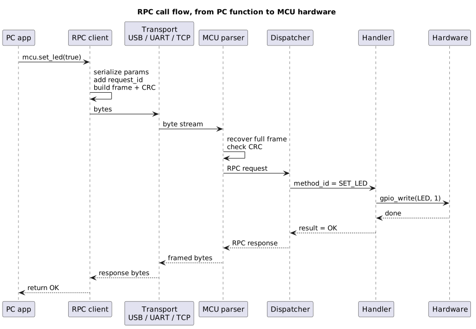
A call begins as a function on the PC, becomes a sequence of bytes, passes through the firmware parser, and returns as a response.
What is an RPC?
An RPC is a procedure call that crosses a communication boundary.
The boundary may separate:
- two processes;
- two computers;
- a client and a remote service;
- two containers or virtual machines;
- a PC and an embedded device.
When we call a local function, the code and its data reside in the same execution environment. A remote function lives elsewhere: we cannot jump directly to its memory address, so the call must be represented as a message.
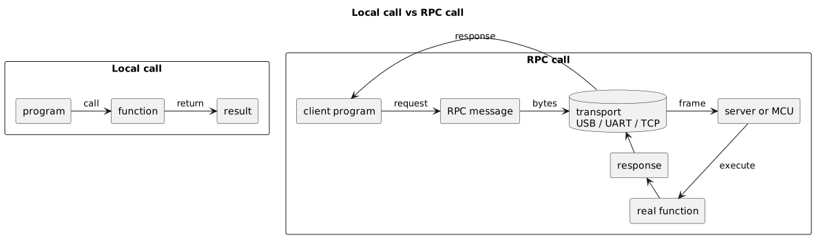
A local call remains inside the same process. An RPC crosses a transport, is interpreted by the remote system, and produces a response.
The purpose of RPC is to simplify this interaction. Code on the PC may look like a normal call:
temperature = mcu.get_temperature(3)Under that single line, however, at least four operations take place:
- the parameters are serialized;
- the request is placed inside a frame;
- the frame is transmitted and interpreted by the firmware;
- the result travels back along the reverse path.
The local syntax is therefore an abstraction. The semantics remain those of remote communication, in which the other side may respond late, return an error, reboot, or become unreachable.
The main elements
RPC communication normally includes a client, a server, a contract, a transport layer, and code that converts calls into messages.
Client and server
The client sends the request. In the scenario discussed in this article, it is usually the application running on the PC:
read the temperature from sensor 3set the motor PWM to 1200turn on the status LEDThe server receives the request and performs the operation. In this case, it is the MCU firmware, which exposes functions similar to the following:
float read_temperature(uint8_t sensor_id);void set_motor_pwm(uint16_t value);void set_led_state(bool on);The terms client and server describe the roles within a single interaction, not necessarily the type of machine. The MCU may also generate spontaneous events directed to the PC, as we will see later.
Contract
The contract establishes which methods exist, which parameters they accept, and which results or errors they can return:
getTemperature(sensor_id: uint8) -> temperature: floatsetLed(state: bool) -> ok | errorgetFirmwareVersion() -> major, minor, patchThe PC and the MCU must interpret this contract in the same way. If the PC sends a 32-bit integer while the MCU reads two 16-bit values, the communication may be formally valid but semantically incorrect.
The contract may be documented manually or described through an Interface Definition Language, usually abbreviated as IDL. gRPC, for example, commonly uses Protocol Buffers to define services and messages and to generate code for different languages.
Stub, proxy, and dispatcher
The PC-side stub or proxy exposes the interface used by the application:
mcu.set_led(True)temperature = mcu.get_temperature(3)Behind these calls, the library assigns an identifier, serializes the parameters, builds the frame, sends it, and waits for the response.
A corresponding component runs on the MCU. The dispatcher interprets the requested method and invokes the appropriate handler:
switch (request.method_id) { case RPC_GET_TEMPERATURE: handle_get_temperature(&request, &response); break; case RPC_SET_LED: handle_set_led(&request, &response); break; default: rpc_set_error(&response, RPC_ERR_UNKNOWN_METHOD); break;}Transport
The transport carries bytes from one endpoint to the other. In distributed systems it may be based on TCP, HTTP/2, or TLS. Between a PC and an MCU, it may instead use:
- UART;
- USB CDC ACM;
- a vendor-specific USB class;
- USB HID;
- Ethernet or Wi-Fi;
- BLE;
- CAN or RS-485;
- SPI or I2C, in suitable architectures.
RPC does not identify the cable or the peripheral. It describes how requests, responses, and errors are organized; USB, UART, or TCP are the means over which those messages travel.
The path of a call
Suppose we want to expose this firmware function:
float get_temperature(uint8_t sensor_id);On the PC we write:
temperature = mcu.get_temperature(sensor_id=3)The RPC library converts the call into a logical request:
method: get_temperaturesensor_id: 3request_id: 42In a human-readable format, it might look like this:
{ "jsonrpc": "2.0", "id": 42, "method": "get_temperature", "params": { "sensor_id": 3 }}JSON-RPC 2.0 uses fields such as method, params, and id. The identifier makes it possible to associate the response with the correct request, while a notification without an id does not expect a response.
The logical document must then become a sequence of bytes. This transformation is called serialization and may use JSON, Protocol Buffers, CBOR, MessagePack, or a proprietary binary format.
Serialization alone does not necessarily establish where a message starts and ends on the transport. This is the role of framing, which adds the information required to delimit and validate each packet.
The firmware receives the bytes, reconstructs the frame, verifies its integrity, decodes the payload, and invokes the handler. The result is then serialized and sent back over the same path:
{ "jsonrpc": "2.0", "id": 42, "result": { "temperature": 24.7 }}If an error occurs, the response should distinguish at least the category and the detail useful to the caller:
{ "jsonrpc": "2.0", "id": 42, "error": { "code": -32001, "message": "Sensor unavailable", "data": { "reason": "SENSOR_NOT_FOUND" } }}What actually travels over the channel
When we write:
value = mcu.get_temperature(sensor_id=3)we are not transferring a function. We are transferring a description of the call.
In JSON-RPC 2.0, a valid request contains at least jsonrpc and method. The params field is optional and may contain a positional array or an object with named parameters. The id field is present only when the caller expects a response:
{ "jsonrpc": "2.0", "id": "pc-42", "method": "get_temperature", "params": { "sensor_id": 3 }}A successful response contains the same id and a result field:
{ "jsonrpc": "2.0", "id": "pc-42", "result": { "temperature": 23.7, "unit": "C" }}A failed response contains error instead. In JSON-RPC, result and error are mutually exclusive, and error.code must be an integer. Method names beginning with rpc. are reserved for the standard and its extensions. A symbolic name such as SENSOR_UNAVAILABLE may be kept inside error.data:
{ "jsonrpc": "2.0", "id": "pc-42", "error": { "code": -32001, "message": "Sensor unavailable", "data": { "reason": "SENSOR_UNAVAILABLE", "sensor_id": 3 } }}It is important to distinguish this standard format from a custom protocol. A message such as:
{ "type": "request", "id": "pc-42", "method": "get_temperature", "params": {}}may be perfectly valid for our project, but the type field is not part of the JSON-RPC 2.0 core. In that case we are designing an RPC envelope inspired by JSON-RPC, not necessarily a strictly interoperable implementation of the standard.
This distinction avoids several misunderstandings. The standard defines the semantics of RPC documents; our protocol must still define framing, transport, limits, authentication, sessions, and behavior after a disconnection.
Bidirectional RPC: the PC and MCU can call each other
In the simplest case, the PC sends requests and the MCU responds. The channel can, however, be bidirectional: the MCU may also initiate a call to the PC.
Suppose the firmware needs to ask the application to save a measurement:
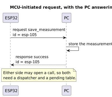
The microcontroller can open a call too: the PC runs the handler and answers with the same identifier.
The request may look like this:
{ "jsonrpc": "2.0", "id": "esp-105", "method": "save_measurement", "params": { "temperature": 23.7, "unit": "C" }}The PC responds by reusing the same identifier:
{ "jsonrpc": "2.0", "id": "esp-105", "result": { "saved": true }}The terms client and server therefore become roles associated with a single call. When the PC sends set_led it is the client and the MCU is the server; when the MCU sends save_measurement, the roles are reversed.
To support this architecture properly, both endpoints need:
- an always-active receiver;
- a message decoder and classifier;
- a dispatcher for methods exposed locally;
- a table of locally initiated pending requests;
- an identifier generator;
- timeouts, errors, and state cleanup;
- a transmission queue that serializes access to the transport.
Avoiding deadlocks and reentrancy
Bidirectionality introduces a less obvious edge case.
Suppose the PC sends start_calibration. While executing the handler, the MCU asks the PC to run confirm_user_present and waits synchronously for the response. If the PC thread that should read and dispatch messages is already blocked while waiting for start_calibration to complete, nobody will process the reverse request coming from the MCU.
The result is a distributed deadlock:
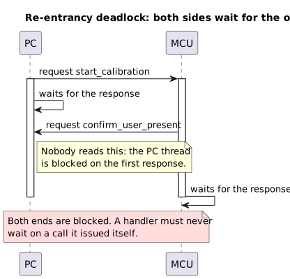
If a handler waits for the response to a request it issued itself, both sides stay blocked.
The solution is to separate the reader loop from application calls. The task receiving frames must continue reading and classifying messages even while other parts of the program wait for a response. Long-running handlers should also be moved to a queue or dedicated tasks instead of being executed directly inside the receive callback.
In substance, a full-duplex channel is not enough. The software architecture must also be genuinely concurrent.
Why the PC-MCU case is special
Two servers normally have powerful CPUs, abundant memory, sockets, filesystems, and advanced diagnostic tools. An MCU may instead have:
- only a few kilobytes of RAM;
- limited flash and computing power;
- small receive buffers;
- real-time constraints;
- interrupts and DMA to coordinate;
- power-consumption limits;
- unexpected resets or watchdogs;
- slow or noisy links.
Consequently, choosing a format and sending data is not enough. We must establish what happens when half a frame arrives, the buffer fills up, the MCU reboots, or a response is lost.
In the embedded world, the protocol is not an implementation detail: it is part of the system architecture.
The complete stack
An RPC between a PC and an MCU can be divided into layers:
- application: “read the temperature” or “set the PWM”;
- RPC contract: methods, parameters, results, and errors;
- serialization: conversion of data into bytes;
- framing: delimitation, length, escaping, and integrity checking;
- transport: UART, USB, TCP, CAN, or another channel;
- drivers and operating system: serial port,
libusb, WinUSB,tty, or COM port; - physical layer: cable, transceiver, and electrical signals.
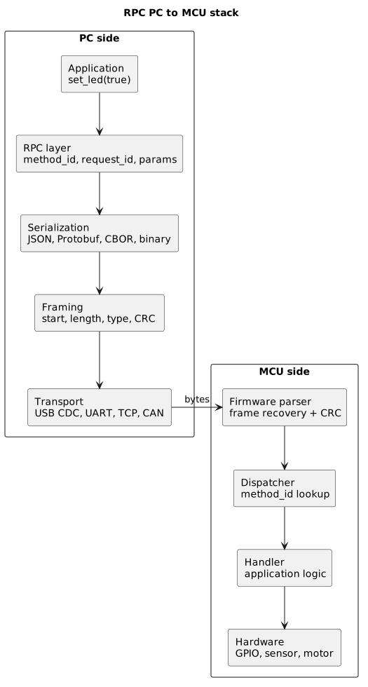
The stack separates the application intent from the contract, framing, transport, and firmware logic.
Each layer solves a different problem. The application expresses:
set_led(true)The RPC layer represents it as:
method_id = 0x0003request_id = 42payload = 01Framing adds length, message type, and an integrity check. The transport carries the frame to the MCU, while the firmware interprets it and finally calls:
gpio_write(LED_PIN, 1);This separation makes it possible, for example, to replace USB CDC with UART without rewriting the application handlers.
Designing a minimal protocol
Suppose we define a simple binary protocol. A frame might contain:
| Field | Size | Role |
|---|---|---|
| MAGIC | 1 byte | marks the start of a frame |
| LENGTH | 2 bytes | length of the payload that follows |
| TYPE | 1 byte | request, response, notification or event |
| CORRELATION_ID | 2 bytes | ties a response to its request |
| PAYLOAD | N bytes | the data itself |
| CRC16 | 2 bytes | validation of the whole frame |
In this example:
- MAGIC helps identify the beginning of a frame;
- LENGTH indicates the number of bytes from
TYPEthrough the end ofPAYLOAD; - TYPE distinguishes requests, responses, errors, and events;
- CORRELATION_ID connects a response to its request; in uncorrelated messages it may be zero or follow a protocol-specific rule;
- PAYLOAD contains the method, parameters, or result;
- CRC16 detects accidental frame corruption.
The message types may be defined as follows:
#define RPC_TYPE_REQUEST 0x01#define RPC_TYPE_RESPONSE 0x02#define RPC_TYPE_ERROR 0x03#define RPC_TYPE_EVENT 0x04A request payload contains at least the method and its parameters:
| Field | Size | Role |
|---|---|---|
| METHOD_ID | 2 bytes | which method to invoke |
| PARAMS | N bytes | the serialized parameters |
For example:
#define RPC_GET_VERSION 0x0001#define RPC_GET_TEMPERATURE 0x0002#define RPC_SET_LED 0x0003#define RPC_SET_PWM 0x0004#define RPC_REBOOT 0x0005A request and its response might be represented as:
REQUEST request_id = 42 method_id = RPC_SET_LED params = 01RESPONSE request_id = 42 status = OKThe real format must also define field endianness, the CRC algorithm, which bytes are covered by the calculation, the maximum payload size, and the behavior when invalid data is received.
Request IDs, correlation, and lifecycle
The request_id associates each response with the call that generated it.
Suppose the PC sends three requests:
id=10 -> read temperatureid=11 -> read voltageid=12 -> read firmware versionThe MCU may complete them in a different order:
id=12 -> firmware versionid=10 -> temperatureid=11 -> voltageWithout an identifier, the PC could not correlate responses when calls are concurrent.
How unique must an ID be?
An identifier does not necessarily need to be unique for the entire lifetime of the product. It must, however, be unambiguous within the scope in which it is used.
The practical rule is:
an ID must not be reused while a pending request with the same IDstill exists in the same sessionAfter the call completes, the identifier may be reused. Reusing it too quickly, however, may cause a late response to be mistaken for a new request. For this reason, it is useful to:
- use a sufficiently large counter, such as 32 or 64 bits;
- avoid immediately reusing timed-out IDs;
- discard and log responses referring to unknown IDs;
- clear the pending-request table when the session changes;
- associate the connection with a
session_idorboot_idwhen resets are frequent.
With a 16-bit counter, wrap-around is not an error by itself. It becomes one if the new value matches a request that is still pending or a late response that may still arrive.
Numeric or string IDs?
JSON-RPC allows string or numeric identifiers and generally discourages null. For a binary protocol, an integer is more compact. During debugging, a string may be easier to read:
{ "id": "pc-42", "method": "get_status"}A bidirectional system may use distinct prefixes:
PC: pc-1, pc-2, pc-3ESP32: esp-1, esp-2, esp-3Prefixes are not mandatory. If each endpoint keeps a separate table for the requests it initiated and the message type clearly distinguishes requests from responses, 42 sent by the PC and 42 sent by the MCU can coexist without conflict.
Separate namespaces are still useful for:
- making logs easier to read;
- passing through bridges or routers that combine multiple channels;
- diagnosing incorrectly classified messages;
- avoiding ambiguity in custom implementations.
The pending-request table
When the PC sends a request, it stores at least:
ID Method Sent Deadline Statepc-41 get_version 14:30:01.100 14:30:01.600 waitingpc-42 read_temperature 14:30:02.000 14:30:02.200 waitingWhen this response arrives:
{ "jsonrpc": "2.0", "id": "pc-42", "result": { "temperature": 23.7 }}the receiver:
- looks up
pc-42in the table; - verifies that the session is still valid;
- delivers the result to the waiting call;
- marks the request as completed;
- removes or archives the entry.
If the response does not arrive before the timeout, the caller receives an error and the entry is removed. Any later response must be treated as a late response: it is normally logged and discarded, not associated with a new request.
Session, boot ID, and stale responses
The request_id alone does not solve the case in which one endpoint reboots.
Suppose the PC sends id=17, the MCU resets, and the PC reconnects the port. If the firmware restarts its counter from 1, the value 17 may appear again. A frame still sitting in a queue, or a response from the previous session, must not be accepted as current.
An initial handshake may therefore return:
{ "protocol_version": 2, "session_id": "7f4a9c21", "boot_id": 184, "max_pending_requests": 4, "max_payload_size": 256}The session_id identifies the current logical connection; the boot_id changes whenever the MCU starts. These fields are not part of JSON-RPC 2.0, but they are often useful in an application envelope or during negotiation.
Request states
A real request passes through more states than a simple function suggests:
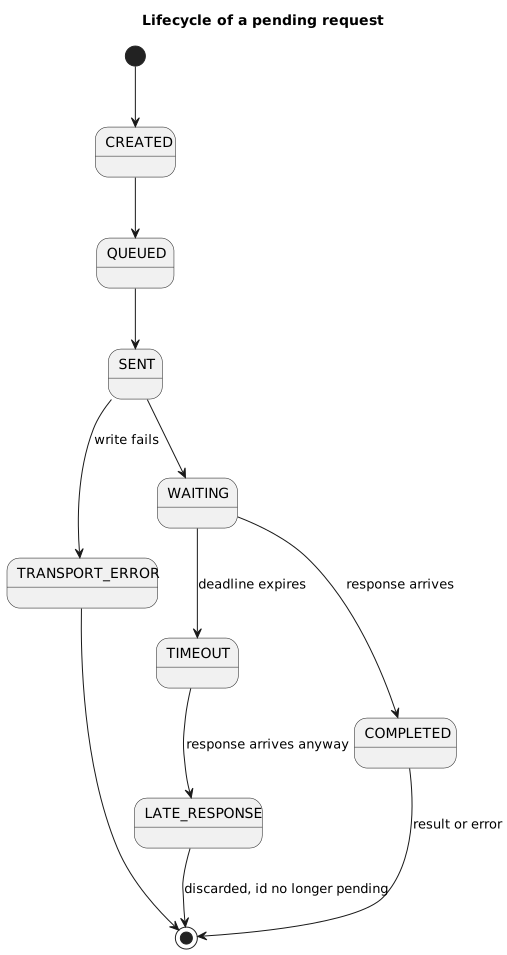
The life cycle of a pending request: every terminal state releases its entry from the pending table.
This state machine helps clarify where failures occurred. A timeout is not the same as a rejected command, and a completed write on the PC does not prove that the firmware handler ran.
Framing: reconstructing messages
UART, TCP, and the serial interface exposed by USB CDC present a byte stream to the application. A single read() does not necessarily correspond to a complete frame:
PC sends:[frame A][frame B][frame C]MCU receives:first read: half of frame Asecond read: end of frame A + beginning of frame Bthird read: end of frame B + frame CThe parser must therefore accumulate bytes and reconstruct messages. Several strategies are available.
Length prefix
The frame declares its own size at the beginning:
[LENGTH][PAYLOAD][CRC]This solution is compact and efficient. A corrupted or unvalidated length, however, may cause loss of synchronization or excessive memory requests. The parser must always reject values larger than the configured maximum.
Delimiter and escaping
A reserved value marks the end of the frame:
[PAYLOAD_ESCAPED][END]If the delimiter appears in the data, it must be encoded through escaping. SLIP, for example, uses the special END and ESC characters. It provides framing, but it does not by itself define addressing, message type, or integrity checking.
Newline-delimited JSON
For a human-readable protocol, each JSON document can end with a newline character:
{"jsonrpc":"2.0","id":"pc-1","method":"get_status","params":{}}\n{"jsonrpc":"2.0","method":"button_pressed","params":{"button":1}}\nThe receiver accumulates bytes until it encounters \n. This approach is simple and convenient for prototypes, terminals, and logs.
It is still necessary to define:
- a maximum line length;
- what to do with invalid UTF-8;
- whether
\r\nis accepted in addition to\n; - how to recover after a malformed line;
- whether whitespace or empty lines are valid.
Newlines inside a JSON string are encoded as \\n, so they do not match the physical line delimiter. The main problem is a line without a terminator that continues filling the buffer: the parser must abort it once it exceeds max_message_size.
Binary length prefix
In production, it is common to prepend a fixed-size length field:
[uint32 length][payload of length bytes]The field may indicate only the payload or the complete frame. The choice is secondary; what matters is documenting it together with the endianness.
The parser follows a simple sequence:
1. accumulate 4 bytes2. decode length3. reject length > MAX_PAYLOAD4. accumulate exactly length bytes5. deliver the payload to the decoderA length prefix does not replace validation. If the field is corrupted, the receiver may lose synchronization; an initial magic value, a CRC, and a resynchronization strategy help it recover.
COBS
Consistent Overhead Byte Stuffing, or COBS, transforms a sequence so that it does not contain a chosen value, often 0x00. That value can then be used as a reliable frame delimiter.
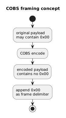
COBS removes the reserved value from the payload and makes it possible to use, for example, 0x00 as a separator between frames.
COBS is interesting for embedded protocols because it has limited overhead and makes it possible to find the next boundary after an error.
HDLC-style framing
Another solution uses a delimiting flag, escaping, and an integrity check:
0x7E payload_escaped crc 0x7EIf 0x7E or the escape byte appears in the content, it is replaced with an encoded sequence. Here too, the protocol must document exactly which bytes are escaped and which bytes are covered by the CRC.
WebSocket: message boundaries and fragmentation
WebSocket introduces the concept of a message, so it does not expose a plain byte stream like TCP. It is therefore possible to carry one RPC document per WebSocket message.
Keep one distinction in mind: a WebSocket message may consist of multiple frames. Some APIs reassemble the entire message before delivering it to the application; others expose successive chunks. Espressif's WebSocket client, for example, may generate multiple events when a message exceeds the buffer size.
Consequently, code must not assume that every callback always contains a complete JSON document. The implementation should inspect at least:
- the fragment offset;
- the expected total length;
- the initial opcode;
- the end-of-message flag;
- the maximum accepted size.
WebSocket solves part of the application-framing problem, but it does not remove memory limits or the need to reassemble fragmented data according to the API being used.
CRC and frame validation
Electrical noise, lost bytes, buffer overflow, and desynchronization may corrupt a frame. An integrity check makes it possible to detect many of these conditions.
On UART or RS-485, an application-level CRC is often very useful. USB and TCP already provide checks and retransmissions at lower layers, so adding another CRC is not automatically necessary. It may still be useful for detecting errors introduced by framing, memory, intermediate bridges, or payload storage. The decision therefore depends on the actual error model, not merely on the presence of a cable.
[HEADER][PAYLOAD][CRC16]The receiver recalculates the CRC over the bytes defined by the protocol and compares it with the transmitted value:
if (crc_received != crc_calculated) { discard_packet(); rpc_record_transport_error(RPC_ERR_BAD_CRC);}In general, it is safer to discard a corrupted frame without attempting to interpret its fields. Sending an error response only makes sense when addressing and correlation are still trustworthy and the protocol explicitly defines that behavior.
A simple checksum may be enough during a prototype, while a protocol intended to operate over real links often benefits from a properly selected and documented CRC.
A CRC does not provide cryptographic security: it detects accidental errors, but anyone intentionally modifying a message can also recalculate the CRC.
Choosing the serialization format
The choice between JSON, Protocol Buffers, CBOR, and a proprietary format affects memory, bandwidth, development tools, and future compatibility.
JSON
JSON is readable and easy to inspect:
{ "id": 12, "method": "set_pwm", "params": { "channel": 1, "value": 1200 }}It is suitable for prototypes and MCUs with sufficient resources. It is, however, verbose, requires textual conversions, and may involve non-negligible parsing time, temporary memory, and processing costs.
Protocol Buffers
Protocol Buffers uses a schema and produces compact binary messages. It also supports code generation for different languages and, when designed carefully, allows the format to evolve while retaining a degree of compatibility.
message RpcRequest { uint32 id = 1; uint32 method = 2; bytes payload = 3;}message RpcResponse { uint32 id = 1; uint32 status = 2; bytes payload = 3;}On microcontrollers, an implementation such as nanopb can be used; it is designed for systems with RAM and ROM constraints. The tradeoff is a stronger dependency on generation tools and a runtime library.
CBOR
CBOR provides a rich binary data model, with goals that include compact messages, small implementations, and extensibility. It can be useful when more flexibility than a rigid schema is desired without paying the full verbosity cost of JSON.
A reliable library must still be selected, and a profile of the format should be defined: accepting every valid CBOR representation may unnecessarily increase parser complexity.
Proprietary binary format
A custom-designed format permits small parsers and complete control:
method_id: 0x0004channel: 0x01value: 0x04B0It is often suitable for highly constrained MCUs, but it requires a rigorous specification, dedicated debugging tools, and a versioning plan. Initial efficiency does not compensate for an ambiguous protocol that cannot evolve.
In substance, there is no universally superior choice. JSON favors inspectability and development speed; Protocol Buffers and CBOR provide more compact formats; a proprietary binary format maximizes control at the cost of greater design effort.
Endianness, alignment, and types
A binary protocol must explicitly define:
- the endianness of multibyte integers;
- the representation of signed numbers;
- the format of floating-point values;
- units of measurement;
- the valid range of every field;
- the handling of strings and lengths.
Sending a C structure directly is fragile:
typedef struct { uint8_t id; uint32_t value;} packet_t;uart_write((uint8_t*)&packet, sizeof(packet));The compiler may insert padding, alignment may differ between architectures, and endianness may change. Any uninitialized bytes may also be transmitted.
It is preferable to serialize each field according to explicit rules:
buffer[0] = id;buffer[1] = (uint8_t)(value & 0xFFu);buffer[2] = (uint8_t)((value >> 8) & 0xFFu);buffer[3] = (uint8_t)((value >> 16) & 0xFFu);buffer[4] = (uint8_t)((value >> 24) & 0xFFu);Alternatively, a format that already defines these conventions can be adopted.
Firmware architecture
On the microcontroller, it is useful to separate reception, framing, serialization, and application logic.
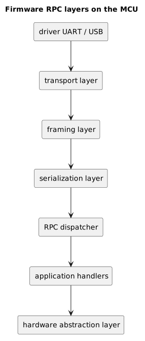
Driver, transport, parser, dispatcher, and handlers remain separate, so each layer can be verified and replaced without involving the others.
Reception and buffers
Bytes may arrive through interrupts, DMA, or USB-stack callbacks. These contexts should do as little work as necessary: acquire the data, update indices, and signal that new bytes are available.
Parsing and handler execution may take place in the main loop or an RTOS task. A ring buffer separates the peripheral's pace from the parser's pace, provided that a maximum size and an overflow policy are defined.
State-machine parser
A state machine works well with a stream that may arrive in fragments:
typedef enum { WAIT_MAGIC, READ_LENGTH, READ_BODY, READ_CRC} parser_state_t;The parser advances only when the required bytes are available:
WAIT_MAGIC -> look for the beginning of the frameREAD_LENGTH -> read and validate the lengthREAD_BODY -> accumulate the expected number of bytesREAD_CRC -> verify integrity
Reception remains lightweight; the parser reconstructs and validates a complete frame before delivering it to the dispatcher.
The parser must validate every length before reserving or copying memory and must be able to resynchronize after corrupted data. Only a complete and valid frame may reach the dispatcher.
Dispatcher and handlers
The dispatcher maps the method_id to an application function:
void rpc_dispatch(rpc_request_t const* req, rpc_response_t* res) { switch (req->method_id) { case RPC_GET_VERSION: handle_get_version(req, res); break; case RPC_GET_TEMPERATURE: handle_get_temperature(req, res); break; case RPC_SET_LED: handle_set_led(req, res); break; default: rpc_set_error(res, RPC_ERR_UNKNOWN_METHOD); break; }}Handlers should not know about the transport. handle_set_led() should receive already validated parameters and produce a logical result without reading directly from UART or constructing USB packets.
This separation makes the firmware easier to test and allows the same contract to be reused over different transports.
The PC-side library
The protocol should also be isolated inside a library on the PC:
mcu = McuRpcClient(port="/dev/ttyACM0")version = mcu.get_version()temperature = mcu.get_temperature(3)mcu.set_led(True)The library is responsible for:
- assigning the
request_id; - validating and serializing parameters;
- building and sending the frame;
- accumulating received bytes;
- correlating responses with requests;
- applying timeouts and retry policies;
- translating protocol errors;
- managing disconnection and reconnection.
The application can therefore work with a clean interface without repeatedly duplicating read() calls, CRC calculations, and buffer management.
This is the main practical benefit of RPC: communication complexity remains confined to dedicated components, while application code expresses the operation to perform.
The RPC engine inside both endpoints
At this point we can describe the real behavior of the RPC engine. Every complete message is first classified and only then delivered to the correct component.
In a protocol with an explicit type:
void rpc_on_message(rpc_message_t const* msg) { switch (msg->type) { case RPC_MSG_RESPONSE: case RPC_MSG_ERROR: rpc_complete_pending(msg); break; case RPC_MSG_REQUEST: rpc_enqueue_request(msg); break; case RPC_MSG_NOTIFICATION: rpc_enqueue_notification(msg); break; case RPC_MSG_NOTIFICATION_ACK: rpc_complete_event_delivery(msg); break; default: rpc_record_protocol_error(RPC_ERR_UNKNOWN_TYPE); break; }}The receive callback does not execute a slow handler directly. It places the request in a queue instead. A dedicated task validates parameters, executes the method, and builds the response.
A fixed table on the microcontroller
A dynamic map is natural on the PC. On an MCU, a fixed-size table may be preferable:
#define RPC_MAX_PENDING 4typedef enum { RPC_PENDING_FREE, RPC_PENDING_WAITING, RPC_PENDING_COMPLETED, RPC_PENDING_TIMED_OUT} rpc_pending_state_t;typedef struct { uint32_t id; uint32_t deadline_ms; uint16_t method_id; rpc_pending_state_t state; rpc_callback_t callback; void* user_data;} rpc_pending_t;static rpc_pending_t pending[RPC_MAX_PENDING];When the MCU calls the PC:
rpc_status_t rpc_call_pc( uint16_t method_id, uint8_t const* payload, size_t payload_len, uint32_t timeout_ms, rpc_callback_t callback, void* user_data) { rpc_pending_t* slot = rpc_pending_allocate(); if (slot == NULL) { return RPC_ERR_TOO_MANY_PENDING; } slot->id = rpc_next_request_id(); slot->method_id = method_id; slot->deadline_ms = monotonic_ms() + timeout_ms; slot->state = RPC_PENDING_WAITING; slot->callback = callback; slot->user_data = user_data; if (!rpc_send_request(slot->id, method_id, payload, payload_len)) { rpc_pending_release(slot); return RPC_ERR_TRANSPORT; } return RPC_OK;}This function does not block. The reader task will deliver the response to the associated callback. The main loop may also scan the table and mark entries as expired after their deadlines. In real code, comparisons between 32-bit timestamps must handle wrap-around safely, for example by comparing the difference as a signed integer rather than using a simple now > deadline test.
Pending map on the PC
A simplified asynchronous Python implementation may look like this:
import asyncioimport itertoolsclass RpcPeer: def __init__(self, transport): self.transport = transport self.pending = {} self.ids = itertools.count(1) async def call(self, method, params, timeout=0.5): request_id = f"pc-{next(self.ids)}" loop = asyncio.get_running_loop() future = loop.create_future() self.pending[request_id] = future request = { "jsonrpc": "2.0", "id": request_id, "method": method, "params": params, } try: await self.transport.send_message(request) return await asyncio.wait_for(future, timeout) finally: self.pending.pop(request_id, None) def handle_response(self, message): request_id = message.get("id") future = self.pending.get(request_id) if future is None: self.log_late_or_unknown_response(message) return if "error" in message: future.set_exception(RpcRemoteError(message["error"])) else: future.set_result(message["result"])The call() method must not also be responsible for reading the transport. A separate reader task continues receiving messages and invokes handle_response() or the dispatcher for reverse requests.
A single transmission queue
Even when multiple tasks generate responses, events, and calls, it is prudent to use a single point that writes to the transport:
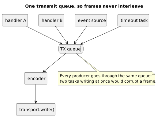
Every producer goes through the same transmit queue, or two tasks could interleave the bytes of two frames.
This prevents two frames from being interleaved at byte level and allows priorities to be managed explicitly. Urgent messages may use separate queues or a priority queue, provided that ordinary messages are not starved.
Requests, responses, notifications, and events
Communication is not always a simple request-response sequence.
A request expects a correlated response:
{ "jsonrpc": "2.0", "id": "pc-7", "method": "set_led", "params": { "state": true }}Response:
{ "jsonrpc": "2.0", "id": "pc-7", "result": { "ok": true }}A JSON-RPC notification, on the other hand, is a request without an id:
{ "jsonrpc": "2.0", "method": "button_pressed", "params": { "button": 1 }}The absence of an id indicates that the sender does not expect a response. The receiver must not respond even when the method or parameters are invalid.
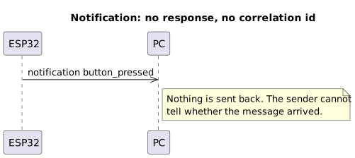
A notification expects no answer: the sender cannot know whether it arrived.
This behavior keeps notifications simple, but it has a consequence: the sender cannot know whether the message was processed successfully.
Application event and RPC notification are not exact synonyms
An event normally describes something that has happened:
button_pressedtemperature_threshold_exceededmotor_fault_detectedA notification instead describes the communication pattern: a one-way message without an RPC response.
An event may therefore be carried as a notification, but it may also use a reliable protocol with acknowledgements, persistence, or replay.
On the PC, a simple event can become a callback:
def on_button_pressed(event): print("Button pressed:", event["button"])mcu.on("button_pressed", on_button_pressed)Sequence number, notify ID, and ACK
Some custom protocols add an identifier to the event:
{ "type": "notification", "notify_id": 81, "method": "motion_detected", "params": { "zone": 2 }}This notify_id is not a JSON-RPC request ID. It may be used to:
- detect duplicates;
- preserve or verify ordering;
- acknowledge delivery;
- resume a stream after reconnection;
- correlate logs and metrics.
The PC may answer with a custom ACK:
{ "type": "notification_ack", "notify_id": 81}The flow becomes:
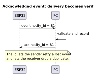
The ack makes delivery verifiable: the sender can retransmit and the receiver can discard duplicates.
If the ACK does not arrive, the MCU may retransmit. The PC must, however, deduplicate, because the original event may have been processed while only the ACK was lost.
This model provides at-least-once delivery in terms of attempts: the event will be sent again until acknowledged, but it may be observed more than once. Approaching at-most-once semantics requires a cache of identifiers that have already been processed. An exactly-once guarantee across resets, power loss, and nonvolatile memory instead requires a much more complex transactional design.
Streams and sequence numbers
A sequence number is useful for a stream:
sample_seq = 1001sample_seq = 1002sample_seq = 1005The gap allows the PC to detect that samples 1003 and 1004 were lost. A sequence number does not prove that missing samples can be recovered: the protocol must state whether they are retained, retransmitted, or simply considered lost.
For every stream, it is useful to define:
- a stream identifier;
- the sample format and units;
- the nominal and maximum frequency;
- the sequence number and wrap-around behavior;
- the timestamp and time domain;
- the overflow policy;
- how the stream starts, stops, and resumes.
Heartbeat and liveness
A heartbeat may indicate that the firmware is still running:
{ "type": "heartbeat", "sequence": 440, "uptime_ms": 913442, "boot_id": 184}Its absence for a certain interval suggests a disconnection or stall, but it does not necessarily identify the cause. Furthermore, an established TCP connection does not by itself guarantee that the remote application is still processing messages. Heartbeats, application timeouts, and keepalive mechanisms solve different problems and should not be confused.
USB in a PC-MCU connection
Before discussing the protocol, it is useful to clarify that “an ESP32 connected through USB” may refer to different architectures. Many boards based on the original ESP32 use an external USB-to-UART bridge: the PC communicates with the bridge, while the MCU sees a normal UART. Some chips in the family instead integrate a fixed-function USB Serial/JTAG peripheral; others expose USB OTG and can use a device stack such as TinyUSB to implement CDC, HID, or vendor-specific classes.
All these solutions may appear as a serial port on the PC, but they do not behave identically. Reset handling, buffers, descriptors, available endpoints, and the ability to customize the device all differ. The RPC layer should therefore depend on an abstract transport backend rather than assume that every USB connector maps to the same firmware peripheral.
In a traditional USB connection, the PC normally acts as the host and the MCU as the device. The host schedules transactions on the bus; the device exposes data and endpoints according to USB rules.
Endpoints are logical points in the device through which data is transferred. On the host side, they are represented through pipes managed by the USB stack.
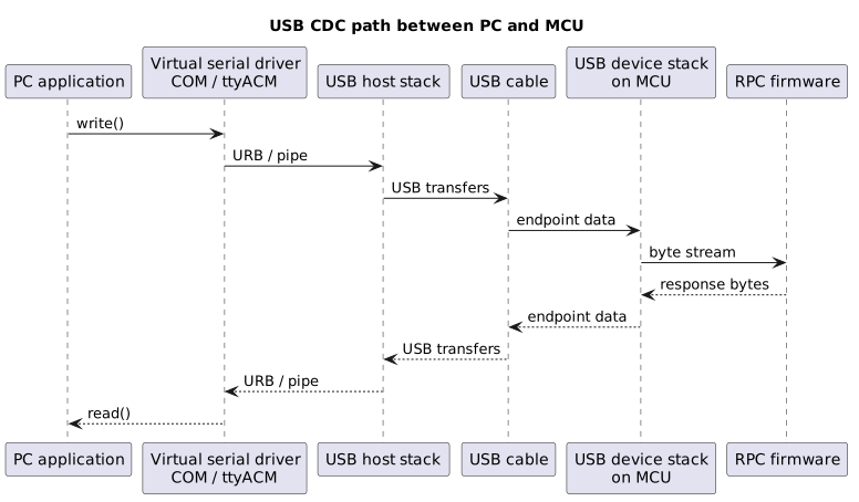
With USB CDC, the application often sees a virtual serial port, while drivers, host and device stacks, endpoints, and firmware operate underneath.
Enumeration and the control endpoint
Every device exposes control endpoint 0. During enumeration:
- the host detects and resets the device;
- it queries endpoint 0 and assigns an address;
- it reads the USB descriptors;
- it identifies classes, configurations, interfaces, and endpoints;
- it selects the appropriate driver;
- it makes the device available to applications.
An MCU configured as USB CDC ACM often appears as a virtual serial port:
COM7on Windows;/dev/ttyACM0on GNU/Linux;/dev/cu.usbmodem...on macOS.
This solution simplifies integration because it normally uses drivers already included in the operating system. It does not, however, remove the need for framing, timeouts, and disconnection handling.
UART and USB CDC as byte streams
Both UART and the serial interface provided by USB CDC require the application to reconstruct messages. A write() call must not be assumed to correspond to a single read() call on the other side.
It is also useful to avoid a terminology ambiguity. UART already uses a physical frame made of a start bit, data bits, optional parity, and stop bits. That frame normally represents a single character, not an application-level RPC message. The framing discussed in this article therefore operates at a higher layer.
With UART, it is also necessary to define:
- baud rate;
- parity and stop bits;
- logic levels and transceivers;
- flow control;
- oscillator tolerance;
- buffer sizes;
- behavior on overflow.
RTS/CTS or software flow control can prevent the transmitter from overwhelming a slower receiver. USB CDC changes the electrical and transport details, but finite buffers, latency, timeouts, port resets, and device disconnections remain.
Timeouts, deadlines, retries, and idempotency
A call may fail because the MCU is busy, the cable was disconnected, the firmware rebooted, or the response was lost. The client must therefore apply a timeout:
send request id=42wait at most 200 msno response -> timeoutThe correct value depends on the transport and the expected maximum duration of the operation. A single timeout for every method is simple, but it may be too aggressive for slow commands and too permissive for immediate ones.
A monotonic clock should be used to measure deadlines. Wall-clock time may change because of NTP synchronization, time-zone changes, or manual adjustments, so it is not suitable for calculating call duration.
A timeout does not reveal whether the command ran
This is one of the most important properties of RPC.
Suppose the PC sends dispense_liquid(10). The MCU executes the command, but the response is lost. From the PC's point of view, the call times out:
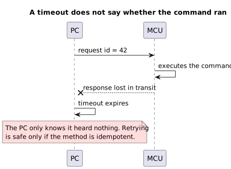
A timeout only says that nothing came back, not whether the command ran.
The timeout means only this: the caller did not receive a response before the limit. It does not automatically mean that the method never started or never completed.
This is what distinguishes a remote call from a local function. After a network error, the real state may be uncertain.
Safe and unsafe retries
After a timeout, a retry may be attempted, but not every operation is safe to repeat.
A command is idempotent when repeated execution produces the same final state:
set_led(true) -> idempotenttoggle_led() -> not idempotentset_motor_speed(1200) -> idempotentincrease_counter() -> not idempotentdispense_liquid(10ml) -> not idempotentA practical policy might be:
| Category | Automatic retry | Note |
|---|---|---|
| read | often yes | consider cost and data freshness |
| set a desired state | often yes | prefer idempotent methods |
| increment or toggle | normally no | may apply the transformation twice |
| irreversible physical action | no, without dedupe | requires a token and MCU-side checking |
| long-running operation | depends | use operation_id and status queries |
Even idempotent operations need limits on attempts and frequency. Aggressive retries may saturate an MCU that is already struggling. Backoff, jitter, and a maximum attempt count help prevent a request storm.
Deduplication through an operation token
For a non-idempotent call, the caller can generate a stable token and reuse it for every attempt:
{ "jsonrpc": "2.0", "id": "pc-44", "method": "dispense_liquid", "params": { "milliliters": 10, "operation_token": "op-8f91a2" }}The MCU temporarily stores the result associated with op-8f91a2. If it receives the same token again, it does not repeat the action and returns the previous result:
first reception of op-8f91a2 -> execute and store resultsecond reception -> do not execute; return cached resultThe cache needs clear limits:
- entry lifetime;
- maximum number of tokens;
- behavior after a reboot;
- optional persistence in flash;
- consistency with the physical or transactional action.
A token stored only in RAM protects against retries within the same session, but not against a reset that occurs after execution and before the response is sent.
Cancellation
A PC-side timeout does not automatically interrupt the firmware handler. For cancellable operations, an explicit message can be defined:
{ "jsonrpc": "2.0", "id": "pc-51", "method": "cancel_operation", "params": { "operation_id": 7 }}Cancellation is normally best effort. The command may arrive after the operation has already completed or after it has crossed a point that can no longer be reversed. The handler should therefore periodically check a cancellation flag and return a precise state:
{ "jsonrpc": "2.0", "id": "pc-51", "result": { "status": "CANCELLED" }}Possible states may include CANCELLED, ALREADY_COMPLETED, NOT_CANCELLABLE, and UNKNOWN_OPERATION. If the caller does not need confirmation, cancel_operation may be sent as a notification without an id, at the cost of not knowing the outcome.
Request ID and operation ID
The request_id correlates the immediate response with a call. The operation_id instead identifies an activity that continues over time:
REQUEST id=pc-50 start_calibration()RESPONSE id=pc-50 accepted operation_id=7EVENT operation_id=7 progress=25EVENT operation_id=7 progress=80EVENT operation_id=7 completed=OKThe two identifiers are not interchangeable. The first lives for the duration of the request; the second may remain valid for minutes, span multiple messages, and support queries such as get_operation_status(7).
Whenever possible, methods should describe the desired state, such as set_motor_speed(1200), rather than relative transformations such as increase_motor_speed(100).
Application and transport errors
“Operation failed” does not contain enough information to diagnose a protocol. It is useful to distinguish at least:
#define RPC_OK 0x00#define RPC_ERR_BAD_FRAME 0x01#define RPC_ERR_BAD_CRC 0x02#define RPC_ERR_UNKNOWN_METHOD 0x03#define RPC_ERR_INVALID_ARGUMENT 0x04#define RPC_ERR_BUSY 0x05#define RPC_ERR_TIMEOUT 0x06#define RPC_ERR_NOT_ALLOWED 0x07#define RPC_ERR_UNSUPPORTED_VER 0x08#define RPC_ERR_INTERNAL 0x09Not all errors belong to the same layer:
| Error | Layer | Meaning |
|---|---|---|
| BAD_CRC | transport | corrupted frame, normally discarded |
| UNKNOWN_METHOD | contract | method not exposed by the firmware |
| INVALID_ARGUMENT | application | invalid parameters |
| BUSY | application | valid request, but resource unavailable |
| NOT_ALLOWED | state/security | command forbidden in the current state |
The PC library may translate these codes into exceptions or typed results while keeping the original detail available for logs.
Versioning and capability discovery
The application and firmware may evolve at different times. The PC must therefore discover the protocol version and the features that are actually available.
An initial call may return:
{ "protocol_version": 2, "firmware_version": "1.3.0", "device": "motor-controller-x1", "capabilities": [ "get_temperature", "set_pwm", "stream_logs" ], "max_payload_size": 256}It is useful to distinguish the firmware version from the protocol version. An internal update does not necessarily imply a contract change.
In JSON-RPC, the jsonrpc field with value 2.0 identifies the JSON-RPC standard version, not the version of our application's methods. The embedded contract needs separate fields such as protocol_version, schema_version, or capabilities.
Some practical rules are:
- do not change the meaning of an existing
method_id; - do not immediately reuse removed identifiers or fields;
- add optional fields when the format permits it;
- define behavior for unknown fields;
- explicitly negotiate incompatible changes;
- declare limits such as
max_payload_sizeand the maximum number of pending requests.
Flow control and backpressure
The PC can produce data much faster than the MCU can process it. Without a control strategy, buffers fill up and frames are lost.
Possible solutions include:
- allowing only one pending request;
- setting a maximum window of
Nrequests; - returning
BUSYresponses or using explicit credits; - ACK and NACK;
- RTS/CTS on UART;
- rate limiting on the PC;
- TX/RX queues with detectable overflow;
- separate limits for commands and events.
For a first embedded protocol, the simplest sequence is often sufficient:
the PC sends one requestwaits for the responsesends the next requestThroughput is lower, but the number of states and edge cases remains limited. Pipelining can be introduced once real measurements show that it is necessary.
Streams also require backpressure. If the PC does not read quickly enough, the protocol must establish whether to drop the oldest samples, stop the stream, or report overflow.
Long-running and real-time operations
The RPC parser must not compromise tasks such as motor control, ADC acquisition, CAN communication, or watchdog handling.
A handler that blocks for several seconds is problematic:
void handle_rpc_request(void) { perform_slow_measurement(); wait_until_complete();}An asynchronous model is often preferable for long-running operations:
REQUEST start_calibration()RESPONSE accepted operation_id=7EVENT progress operation_id=7 value=25%EVENT progress operation_id=7 value=80%EVENT completed operation_id=7 result=OK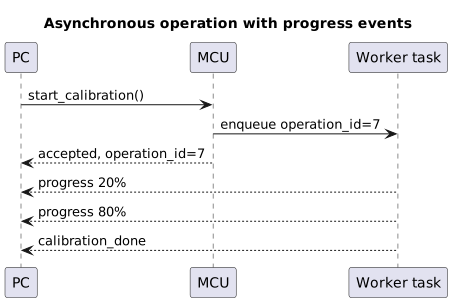
The MCU accepts the command, returns an identifier, and reports progress without blocking the entire system.
The operation_id does not replace the request_id: the former identifies an activity that continues over time, while the latter correlates the immediate response with the call.
Security
A local connection is not automatically trustworthy. The protection required depends on the product and on the consequences of the exposed commands.
We should ask:
- which processes can open the device;
- whether any operations move actuators or modify calibration data;
- whether the protocol permits memory reads or firmware updates;
- which state the machine must be in before accepting a command;
- whether an attacker can observe or alter the channel.
Countermeasures may include:
- operating-system permissions on the device;
- a whitelist of methods available in production;
- strict validation of parameters and machine state;
- rate limiting;
- cryptographic authentication for critical commands;
- signed and verified firmware updates;
- disabling debug interfaces;
- separating operating and maintenance modes.
A generic challenge-response mechanism is not sufficient unless it is built with cryptographic primitives and secure key management. Likewise, a CRC does not authenticate the sender and does not protect against intentional modification.
Limited measures may be acceptable for an internal laboratory tool. A distributed product that controls power, motors, or sensitive data instead requires an explicit threat analysis.
Operating system and drivers
The PC application normally passes through operating-system APIs, drivers, and communication stacks.
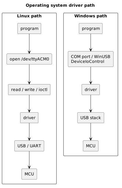
The program uses operating-system APIs and drivers before reaching the peripheral and the MCU firmware.
On GNU/Linux, a serial port is generally exposed as a special file. Calls such as read() and write() transfer data, while ioctl() or dedicated APIs configure device properties.
On Windows, a USB CDC class often appears as a COM port. A vendor-specific class may instead use WinUSB, libusb, or a dedicated driver. DeviceIoControl() also allows applications to send control codes to a driver when the architecture requires it.
These details should remain confined to the library's transport backend so that the RPC interface does not depend on the platform.
RPC does not necessarily mean gRPC
gRPC is a modern RPC framework widely used in distributed systems. It uses HTTP/2 and commonly Protocol Buffers, providing code generation, streaming, and a typed contract.
It is not, however, the only form of RPC and is not always suitable for a small MCU. A complete HTTP/2 stack, optional TLS, and their dependencies may require more RAM, flash, and complexity than the project justifies.
Over a UART or USB CDC connection, RPC may simply mean:
- a documented set of methods;
- requests with parameters;
- responses correlated through an identifier;
- errors, timeouts, and versioning;
- asynchronous events when required.
It is therefore possible to build proprietary RPC over UART, JSON-RPC over a serial link, Protocol Buffers messages over USB, or CBOR over RS-485. The underlying concept remains the same even without gRPC.
RPC, REST, and events
RPC normally describes actions:
get_temperature()set_led(true)start_motor()calibrate_sensor()REST primarily models resources and HTTP operations:
GET /sensors/3/temperaturePUT /leds/1/statePOST /calibrationsAn event system instead describes facts that have already occurred:
button_pressedtemperature_threshold_exceededmotor_fault_detectedIn a PC-MCU connection, RPC is a natural way to issue commands to firmware, while events are better suited to spontaneous notifications from the board. A real protocol may therefore combine requests and responses, events, and streams without forcing everything into the same model.
A complete bidirectional example
Suppose an ESP32 controls an LED, a temperature sensor, a PWM motor, and a button. The PC also exposes methods that the firmware may invoke.
Methods exposed by the MCU:
get_protocol_info() -> version and capabilitiesget_temperature(sensor_id) -> valueset_led(state) -> okset_pwm(channel, value) -> okstart_log_stream(level) -> stream_idstop_log_stream(stream_id) -> okstart_calibration() -> operation_idget_operation_status(operation_id) -> statereboot(mode) -> okMethods exposed by the PC:
save_measurement(value, unit, timestamp) -> savedget_current_time() -> unix_timeconfirm_user_present(message) -> confirmedwrite_log(level, message) -> okEvents generated by the MCU:
button_pressed(button_id, sequence)temperature_alarm(sensor_id, value, sequence)motor_fault(code, sequence)log_line(stream_id, sequence, level, message)operation_progress(operation_id, progress)heartbeat(sequence, uptime_ms, boot_id)1. Connection and negotiation
The PC opens the connection and queries the device:
{ "jsonrpc": "2.0", "id": "pc-1", "method": "get_protocol_info", "params": {}}The MCU responds:
{ "jsonrpc": "2.0", "id": "pc-1", "result": { "protocol_version": 2, "firmware_version": "1.5.0", "device_id": "CTRL-BOARD-A", "session_id": "7f4a9c21", "boot_id": 184, "max_payload": 256, "max_pending_requests": 4, "capabilities": [ "temperature", "pwm", "bidirectional_rpc", "reliable_events", "log_stream", "operation_cancel" ] }}The PC verifies compatibility before sending other commands.
2. The PC turns on the LED
Request:
{ "jsonrpc": "2.0", "id": "pc-2", "method": "set_led", "params": { "state": true }}Response:
{ "jsonrpc": "2.0", "id": "pc-2", "result": { "ok": true, "state": true }}3. The button generates an event
For an unreliable event, the MCU may send a JSON-RPC notification:
{ "jsonrpc": "2.0", "method": "button_pressed", "params": { "button_id": 1, "sequence": 293 }}The PC does not respond.
For an event that must not be lost, the custom protocol may instead use notify_id and an ACK:
{ "type": "notification", "notify_id": 294, "method": "motor_fault", "params": { "code": "OVERCURRENT" }}{ "type": "notification_ack", "notify_id": 294}4. The MCU asks the PC for the current time
The MCU initiates a new RPC over the same channel:
{ "jsonrpc": "2.0", "id": "esp-27", "method": "get_current_time", "params": {}}The PC responds:
{ "jsonrpc": "2.0", "id": "esp-27", "result": { "unix_time": 1785330000, "utc_offset_minutes": 120 }}5. Long-running operation
The PC starts a calibration:
{ "jsonrpc": "2.0", "id": "pc-3", "method": "start_calibration", "params": {}}The MCU quickly accepts the request:
{ "jsonrpc": "2.0", "id": "pc-3", "result": { "accepted": true, "operation_id": 7 }}Progress arrives through events:
{ "jsonrpc": "2.0", "method": "operation_progress", "params": { "operation_id": 7, "progress": 25 }}{ "jsonrpc": "2.0", "method": "operation_completed", "params": { "operation_id": 7, "result": "OK" }}6. Late response
The PC sends get_temperature with a 200 ms timeout. The response arrives after 350 ms:
TX pc-4 get_temperature200 ms -> timeout, pending entry removed350 ms -> RX response pc-4, classified as a late responseThe library records the data for debugging, but does not deliver it to a new call that may have reused the ID.
This example includes the main models without confusing them:
- PC → MCU requests;
- MCU → PC requests;
- correlated responses;
- notifications without responses;
- reliable events with a custom ACK;
- long-running operations identified separately;
- sessions, timeouts, and late responses.
Large payloads and fragmentation
A frame may have a small maximum size, such as 256 bytes, while a configuration or calibration table may be larger.
In this case, a chunked transfer protocol is needed:
TRANSFER_START total_size=2048 transfer_id=5TRANSFER_CHUNK id=5 offset=0 data=...TRANSFER_CHUNK id=5 offset=256 data=...TRANSFER_CHUNK id=5 offset=512 data=...TRANSFER_END id=5 crc32=...The protocol must define:
- chunk size and ordering;
- handling of duplicate and missing chunks;
- timeouts and cancellation;
- integrity checking for each frame and for the complete object;
- optional transfer resumption;
- memory and write limits.
Firmware updates add security requirements: authenticity, image signatures, rollback protection when needed, and safe recovery after an interruption.
Debugging and observability
A binary protocol is difficult to diagnose without dedicated tools. It is useful to provide logs on the PC:
TX id=42 method=SET_LED len=4RX id=42 status=OK time=3.2msand, when possible, firmware logs:
rpc: received method=0x0003 id=42rpc: set_led state=1rpc: response ok id=42A hexadecimal dump helps verify the bytes that were actually transmitted:
TX: 7E 01 00 08 2A 00 03 01 91 C4RX: 7E 02 00 07 2A 00 00 44 12Even more useful is a decoder that interprets the dump according to the specification:
Frame: type: REQUEST id: 42 method: SET_LED state: true crc: okLogs should not significantly alter real-time behavior or expose secrets and sensitive data in production.
Testing
The protocol must also be verified outside the nominal path. Useful tests include:
- a valid frame;
- an invalid CRC;
- truncated or concatenated frames;
- a length above the maximum;
- an unknown
method_id; - an out-of-range parameter;
- a timeout and late response;
- duplicate transmission of the same request;
- an MCU reset during a call;
- an event received while the PC is waiting for a response;
- a stream faster than its consumer;
- USB disconnection and reconnection;
- an unsupported protocol version;
- two simultaneous requests with the same ID in the same direction;
- the same ID used simultaneously in both directions;
- request-ID counter wrap-around;
- a late response after potential ID reuse;
- a
session_idorboot_idchange during a call; - an MCU → PC reverse request while the PC waits for a response;
- a lost ACK followed by retransmission of the same event;
- a duplicate carrying the same
operation_token; - fragmentation of a WebSocket message across multiple callbacks;
- cancellation received before, during, and after the irreversible point.
The parser deserves dedicated tests because it processes external data. Targeted fuzzing can send random sequences, extreme lengths, and malformed frames while verifying that the firmware does not crash, access memory outside buffers, and can resynchronize.
It is also useful to test the parser on the PC, where sanitizers and analysis tools are more convenient, if the implementation can be shared or compiled for both platforms.
Common mistakes
Confusing a read with a message
This code assumes that read() returns exactly one frame:
data = serial.read(64)parse_rpc(data)The client must instead accumulate bytes, extract every complete frame available, and retain any final fragment for the next read.
Transmitting raw C structures
Padding, endianness, alignment, and uninitialized fields make direct transmission of structure memory fragile. Fields must be serialized using a stable representation.
Trusting the received length
A length declared by the frame must never exceed the limits of the buffer or protocol. Validation must take place before any copy or allocation.
Omitting timeouts
Without a timeout, a call may block the application indefinitely. The timeout must also release the state associated with the request without confusing any late response.
Automatically repeating non-idempotent operations
The loss of a response does not imply that the MCU did not execute the command. An automatic retry may duplicate the operation.
Doing too much work in an interrupt
Parsing, serialization, and application handlers should normally run outside interrupt context, except under exceptional and carefully analyzed requirements.
Ignoring events and versioning
A protocol limited to immediate responses becomes difficult to extend with notifications and long-running operations. Likewise, the absence of versioning makes every firmware update fragile.
Confusing request ID, operation ID, and sequence number
The request_id correlates a response, the operation_id identifies a long-running activity, and a sequence number orders events or samples. Reusing one field for all these purposes makes message lifecycles ambiguous.
Treating a timeout as cancellation
When the PC stops waiting, the MCU may continue executing the handler. If the operation must stop, the protocol needs an explicit and cooperative cancellation mechanism.
Blocking the reader loop
A reader that runs slow handlers or synchronously waits for other RPCs can no longer dispatch responses, events, and reverse requests. Reception must remain independent of application execution.
Assuming a WebSocket callback contains a complete message
WebSocket defines messages, but a concrete API may deliver them in multiple fragments. Code must track offsets, total length, and the end-of-message indication instead of passing every callback directly to the JSON decoder.
A recommended practical configuration
For a first protocol between a PC and an ESP32, I would deliberately choose a simple structure:
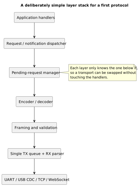
Each layer knows only the one below it, so the transport can change without touching the handlers.
A custom envelope might contain:
{ "protocol_version": 2, "session_id": "7f4a9c21", "type": "request", "id": "pc-100", "method": "set_led", "params": { "state": true }}If JSON-RPC 2.0 is adopted instead, I would preserve the standard envelope and move protocol_version and session_id into the handshake or an outer layer, avoiding an accidental mixture of the standard and a proprietary format.
The minimum rules I would document are:
- maximum frame and payload size;
- maximum number of pending requests in each direction;
- method-specific timeouts or timeout classes;
- ID behavior after timeouts, wrap-around, and reconnection;
- distinction between requests, responses, notifications, reliable events, and streams;
- retry policy for every method;
- deduplication for non-idempotent operations;
- session and
boot_id; - endianness, units, and valid value ranges;
- behavior for unknown fields, methods, and versions;
- priorities, backpressure, and overflow policy;
- authentication and authorization for critical commands;
- debugging modes and redaction of sensitive data.
For a first concrete implementation:
- one pending request per direction is sufficient;
- newline-delimited JSON is excellent during prototyping;
- COBS or a length prefix is more suitable for a binary protocol;
- the reader task must remain active at all times;
- handlers must not block the parser;
- every timeout must use a monotonic clock;
- unknown or late responses should be logged and discarded;
- non-idempotent physical actions must not be retried without a deduplication token.
Only after measuring a real limitation would I introduce extensive pipelining, batching, compression, or additional priority levels. Every new feature increases the number of states to verify and the number of ways in which the two endpoints can diverge.
Conclusion
We have seen how an RPC turns an apparently local call into structured communication. In the PC-MCU case, the path crosses a library, operating system, driver, transport, parser, dispatcher, and finally the hardware controlled by the firmware.
The quality of the interface exposed to the application depends on the precision of the protocol underneath it. Framing, serialization, buffer limits, timeouts, identifiers, versioning, and errors are not secondary details: they define the system's real behavior when something does not proceed as expected.
A first implementation should remain simple. One request at a time, frames with a maximum size, a state-machine parser, clear error codes, and predominantly idempotent methods provide a foundation that is easier to verify. Concurrency, streaming, and fragmentation can be introduced when the use case genuinely requires them.
The most important consideration therefore remains this: an RPC may look like a local function, but it must be designed as remote communication.
In particular, an ID correlates messages but does not guarantee execution; a timeout stops waiting but does not automatically cancel the command; a notification avoids a response but provides no confirmation; a retry improves availability but may duplicate effects. These differences, more than the choice between JSON and binary encoding, define the system's real behavior.
When this boundary is treated with the necessary care, a PC can control an embedded board through a clean interface while the MCU continues to manage the physical world under well-defined constraints and responsibilities. A function remains on the surface; underneath it, there is a precise protocol.
Sources consulted
- JSON-RPC 2.0 Specification
- gRPC introduction
- gRPC core concepts
- Protocol Buffers overview
- RFC 8949: Concise Binary Object Representation
- RFC 9113: HTTP/2
- RFC 1055: Serial Line IP
- Consistent Overhead Byte Stuffing
- nanopb documentation
- Silicon Labs USB CDC ACM documentation
- Microsoft: USB endpoints and pipes
- Microsoft: DeviceIoControl
- Linux ioctl manual page
- Silicon Labs AN0059.0: UART flow control
- Microchip AN1148: Cyclic Redundancy Check
- RFC 9293: Transmission Control Protocol
- RFC 6455: The WebSocket Protocol
- gRPC deadlines
- gRPC retry
- Espressif ESP WebSocket Client documentation
- ESP-IDF UART driver documentation
- ESP-IDF USB Device Stack and CDC-ACM documentation
- ESP-IDF: serial connection through an external USB-to-UART bridge
- ESP-IDF: USB Serial/JTAG Controller Console
- ESP-IDF: ESP32-S3 USB Device Stack
- Wikimedia Commons: Raspberry Pi 3 connected to Lenovo ThinkPad T430 via DSD TECH UART to USB adapter.jpg: image by Cirosantilli2, CC BY-SA 4.0, used as the article cover.

Last updated
2026-06-09.
Article source content/blog/rpc_pc_microcontroller.