Abstract
In the previous article, we saw that a digital image is made of pixels and that a rendering process intended to produce a visible image ends with values written to a framebuffer.
Now let us take a step back.
Before the final pixels exist, before the fragment shader produces its output values, and before the framebuffer is updated, we need to describe what we want to draw.
In computer graphics, especially rasterized 3D graphics, that description often begins with very simple elements: points, lines, and triangles.
A character, a house, a car, a mountain, or a cube is not sent to the GPU as an “object” in the human sense of the word. It is represented by geometric data. That data describes positions, connections, surfaces, and attributes.
The triangle is one of the fundamental primitives in this process. Not because it is particularly beautiful on its own, but because it is simple, stable, and well suited to the graphics pipeline.
Let us therefore see how we move from isolated points to 3D models made of meshes, and why OpenGL works with triangles so often.
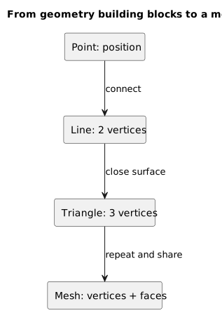
From point to mesh: rasterized geometry organizes positions, connections, and surfaces into simple primitives.
Why This Topic Matters
When we see a 3D model on the screen, we tend to think of it as a single object.
A chair is a chair. A character is a character. A house is a house.
For the GPU, however, this view is too abstract.
The GPU does not receive the concept of a “chair.” It receives numbers.
More precisely, it receives data describing the geometry and how that geometry should be processed:
- positions in space;
- vertex attributes;
- indices;
- primitives.
Textures, material parameters, and shaders take part in rendering, but they are not geometry. Together with the data above, they help build the visual model that we recognize as a chair.
This is why it is important to understand that, in rasterized graphics, a 3D object is often a construction made of many small surfaces.
In most cases, those surfaces are reduced to triangles.
The OpenGL Wiki explains that the basic primitives produced by the pipeline are points, lines, or triangles, and that the vertex stream is divided into an ordered sequence of these primitive types.
If we want to understand OpenGL, then, we first need to understand the elementary geometry it uses to build what we see.
A Simple Idea: Building with Sticks and Cardboard
Imagine that we want to build a small toy house.
We could begin with a few dots drawn on a sheet of paper. Each dot marks an important position: a corner of the roof, a corner of a wall, or a corner of the door.
If we connect two dots, we get a line.
If we connect three dots, we can get a triangle.
If we join many triangles, we can build larger surfaces: walls, roofs, floors, and windows.
This is a useful mental model for understanding 3D graphics.
A complex model does not begin as a magical object. It begins as many positions in space, connected according to a set of rules.
Points define where things are.
Lines can show connections or outlines.
Triangles define surfaces.
Meshes organize all of this into a larger structure.
Coordinates: Saying Where Something Is
To describe a point, we need to say where it is.
In mathematics and computer graphics, we use coordinates.
In 2D, two values are enough:
x, yx usually indicates the horizontal position.
y usually indicates the vertical position.
A 2D point can be written like this:
(3, 2)This means: move 3 units along the x axis and 2 units along the y axis.
In 3D, we add a third coordinate:
x, y, zz represents the third axis. Depending on the convention we choose, it may be interpreted as depth or as the vertical axis.
A 3D point can therefore be written like this:
(3, 2, 5)This point has:
x = 3;y = 2;z = 5.
Of course, these numbers have no absolute meaning on their own. Their meaning depends on the coordinate system we have chosen.
One unit might represent a meter, a centimeter, a kilometer, or simply an abstract measurement in our virtual world.
Axes and Orientation
A 3D coordinate system has three axes. For convenience, we can imagine them like this:
x → horizontaly → verticalz → depthNot every system uses the same orientation, however.
In some contexts, y is the vertical axis. In others, the vertical axis is z.
OpenGL does not dictate which direction must represent “up” in our virtual world. We choose that convention through our transformations and shaders. In the final stages of the pipeline, however, after the perspective division, the normalized coordinates of the visible volume in desktop OpenGL range from -1 to 1 along all three axes.
In that space, we can reason in simplified terms as follows:
positive x → rightpositive y → upz → depthWhen we import models from other software or use different libraries, however, we need to pay attention to their conventions.
This is an important point: geometry is not made only of numbers, but also of how we interpret those numbers.
If two systems use different axes, the same model may appear rotated, flipped, or incorrectly oriented.
Points
A point is a position.
On its own, a point has no size. It has no width, height, or depth. It is simply a location in space.
That is the mathematical definition. When we rasterize a GL_POINTS primitive, OpenGL still needs to cover a finite area of the screen in order to generate fragments.
We can draw points using GL_POINTS primitives.
For example, if we have three vertices, we can tell OpenGL to interpret them as points.
glDrawArrays(GL_POINTS, 0, 3);The glDrawArrays function constructs primitives from data in the enabled vertex attribute arrays. Its mode parameter specifies the type of primitive to construct, such as points, lines, or triangles.
Drawing points can be useful for:
- data visualization;
- debugging positions;
- particle systems;
- scientific representations;
- control points.
Points alone, however, are not enough to build surfaces.
A point may indicate the position of an object's corner, but it does not yet describe a face.
Vertices
In computer graphics, we will encounter the word vertex very often.
A vertex is usually associated with a position, but it is not necessarily only a position.
This distinction matters.
We can think of a geometric point as:
position = (x, y, z)A vertex, by contrast, can also contain other attributes:
positioncolornormaltexture coordinatestangentcustom dataWe can therefore think of a vertex as a small information card.
For example:
Vertex 0position = (-0.5, -0.5, 0.0)color = (1.0, 0.0, 0.0)uv = (0.0, 0.0)The position says where the vertex is.
The color can be used to color the surface.
The uv coordinates can indicate which part of a texture to apply.
The normal can be used in lighting calculations.
This explains why, when we discuss VBOs and attributes later, we will not simply say that we “send points to the GPU.” We will say that we send vertices: structured sets of data.
Lines
In everyday language, we say that a line connects two points. More precisely, the primitive we draw is a line segment bounded by two vertices.
If we have two points:
A = (0, 0, 0)B = (1, 0, 0)we can draw a line from A to B.
In OpenGL, we can use primitives such as GL_LINES.
glDrawArrays(GL_LINES, 0, 2);With GL_LINES, each pair of vertices forms an independent line.
For example, given these vertices:
0, 1, 2, 3OpenGL can construct:
line 0 → vertices 0 and 1line 1 → vertices 2 and 3Lines are useful for:
- debugging;
- grids;
- wireframes;
- coordinate axes;
- outlines;
- modeling tools;
- technical visualizations.
A line does not describe a filled surface, however.
If we want to draw a wall, a floor, or one face of a cube, we need primitives that cover an area.
This is where triangles enter the picture.
Triangles
A triangle is a surface bounded by three vertices that do not lie on the same line.
Three non-collinear points define a plane and bound a triangular face. If they are collinear, or if two of them coincide, the triangle is degenerate and covers no area.
This makes the triangle extremely useful in 3D graphics.
With three points, we can describe a small flat face. By joining many flat faces, we can approximate very complex shapes.
A simple triangle can be described like this:
A = (-0.5, -0.5, 0.0)B = ( 0.5, -0.5, 0.0)C = ( 0.0, 0.5, 0.0)In C++:
float vertices[] = {-0.5f, -0.5f, 0.0f, 0.5f, -0.5f, 0.0f, 0.0f, 0.5f, 0.0f};To draw it as a triangle:
glDrawArrays(GL_TRIANGLES, 0, 3);With GL_TRIANGLES, each complete group of three vertices forms an independent triangle. Any vertices left over that are insufficient to complete another primitive are ignored.
Why Triangles?
It is a reasonable question.
Why not squares? Why not circles? Why not polygons with many sides?
The main reason is that a triangle is simple and unambiguous.
Three non-collinear points always define a plane.
With four points, however, we may run into problems.
Imagine a quadrilateral with four vertices. If all four vertices lie on the same plane, everything is fine. But if one of them sits slightly outside that plane, the surface is no longer perfectly flat.
How should it be drawn at that point?
Triangles avoid this problem.
Every non-degenerate triangle is planar.
Triangles are also easy to interpolate across. When the GPU rasterizes a triangle, it can calculate intermediate values within it: colors, texture coordinates, normals, and other attributes.
This property is fundamental to rendering.
From a Square to Triangles
A square can be divided into two triangles.
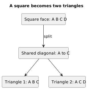
A square is often split along one diagonal: two simple triangles represent the same surface.
Suppose we have these four vertices:
A ----- B| || |D ----- CWe can divide it along a diagonal:
A ----- B| / || / || / |D ----- CThis gives us two triangles:
triangle 1: A, D, Btriangle 2: B, D, CIn code, without indices, we could write:
float vertices[] = { // first triangle -0.5f, 0.5f, 0.0f, // A -0.5f, -0.5f, 0.0f, // D 0.5f, 0.5f, 0.0f, // B // second triangle 0.5f, 0.5f, 0.0f, // B -0.5f, -0.5f, 0.0f, // D 0.5f, -0.5f, 0.0f // C};Then:
glDrawArrays(GL_TRIANGLES, 0, 6);Here we use 6 vertices because each triangle requires 3.
Some vertices are duplicated, however. Vertex B appears twice, as does vertex D.
For a single square, this is not a serious problem. In a complex model, however, needlessly duplicating vertices can become expensive.
That is why indices and EBOs exist. We will examine them in detail later.
Shared Vertices and Indices
Instead of repeating vertices, we can write one list of vertices and a second list of indices.
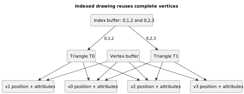
With an index buffer, multiple triangles can reuse the same vertices when their position and attributes match.
Vertices:
float vertices[] = { -0.5f, 0.5f, 0.0f, // 0: A 0.5f, 0.5f, 0.0f, // 1: B 0.5f, -0.5f, 0.0f, // 2: C -0.5f, -0.5f, 0.0f // 3: D};Indices:
unsigned int indices[] = {0, 3, 1, 1, 3, 2};The triangles are now:
triangle 1: vertices 0, 3, 1triangle 2: vertices 1, 3, 2We will use glDrawElements to draw them:
glDrawElements(GL_TRIANGLES, 6, GL_UNSIGNED_INT, 0);The glDrawElements documentation specifies that the function uses a sequence of elements from an index array to construct geometric primitives, while the mode parameter determines which type of primitive to construct.
In this example, we assume that an EBO is associated with the current VAO. The final argument, 0, is not an index: it represents an offset of zero bytes into the index buffer.
This approach allows the same vertices to be reused in several triangles. We must remember, however, that an index selects the complete set of attributes belonging to a vertex, not only its position.
This is essential when working with real meshes.
Meshes
A mesh is a structure that describes the shape of an object through vertices, connections, and faces.
In simple terms, we can say:
In rasterized rendering, a mesh is often a network of triangles that approximates a shape.
In its most essential sense, a mesh contains or describes:
- vertices;
- indices or other connectivity data;
- faces;
- attributes such as normals, colors, and texture coordinates.
A model or file format may then associate materials, submeshes, animation data, and other information with that mesh. This distinction will become clearer shortly.
A cube can be represented as a mesh.
A sphere can be represented as a mesh.
A character can be represented as a mesh.
The level of detail naturally varies.
A cube may require only a few triangles.
A realistic character may require tens or hundreds of thousands.
A Mesh Is Not Always “Smooth”
One interesting detail is that a mesh is made of flat faces, yet it can appear smooth.
Consider a sphere.
A mathematical sphere is perfectly continuous. A mesh, by contrast, can only approximate it with many triangles.
If we use only a few triangles, the sphere will look faceted.
If we use many triangles, it will look smoother.
The impression of smoothness does not depend only on the number of triangles, however. It also depends on normals and shading.
Two spheres with the same geometry can look different if we change how their lighting is calculated.
This is an important point: perceived shape depends not only on geometry, but also on rendering.
Faces
A face is one surface of a mesh.
When working with OpenGL at a low level, we will often think of faces as triangles.
In modeling software, however, we may also see quadrilateral faces or polygons with more sides.
These can be convenient during modeling, but before rendering with a modern OpenGL core profile they must be triangulated: the old primitives dedicated to quadrilaterals and polygons are no longer part of the core profile.
Triangulation means dividing a more complex surface into triangles.
For example, a square face becomes two triangles.
A more complex polygon may become many triangles.
This step matters because the GPU works very well with simple primitives.
OpenGL Primitives
When we issue a draw call in OpenGL, we must specify how the vertices should be interpreted.
Some common values for the mode parameter are:
GL_POINTSGL_LINESGL_LINE_STRIPGL_TRIANGLESGL_TRIANGLE_STRIPGL_TRIANGLE_FANThey are not all used with the same frequency in modern OpenGL, but they help illustrate the idea.
With GL_POINTS, every vertex is a point.
With GL_LINES, every pair of vertices is a line.
With GL_TRIANGLES, every group of three vertices is a triangle.
With GL_TRIANGLE_STRIP, after the first three vertices, every additional vertex produces another triangle by sharing previous vertices.
In other words, the selected mode determines how the ordered vertex stream is divided into basic primitives.
GL_TRIANGLES
GL_TRIANGLES is the simplest mode to understand.
Every three vertices form an independent triangle.
If we have 6 vertices:
0, 1, 2, 3, 4, 5OpenGL constructs:
triangle 1: 0, 1, 2triangle 2: 3, 4, 5This behavior is easy to reason about and very clear.
The drawback is that it may lead us to duplicate vertices if we do not use indices.
For this reason, we often combine:
GL_TRIANGLES + EBOThat is, independent triangles with vertices that can be reused through indices.
GL_TRIANGLE_STRIP
GL_TRIANGLE_STRIP is a more compact way to describe a sequence of connected triangles.
The first three vertices form the first triangle.
Each subsequent vertex then adds another triangle.
With five vertices:
0, 1, 2, 3, 4we get three triangles:
triangle 1: 0, 1, 2triangle 2: 2, 1, 3triangle 3: 2, 3, 4The effective order of the first two vertices alternates for each new triangle. This allows OpenGL to keep the face orientation consistent along the strip. In general, n vertices can produce n - 2 triangles, provided that n is at least 3.
This mode can reduce the number of vertices required, but it makes the structure a little less immediate to reason about.
When starting out, it is simpler to use GL_TRIANGLES.
Once we are more comfortable with the pipeline, the other modes will be easier to understand as well.
Winding Order: The Direction of the Vertices
The order of a triangle's vertices matters.
A triangle can be specified in clockwise or counterclockwise order.
Imagine three vertices:
A, B, CWhen viewed on the screen, their order may turn counterclockwise:
A → B → COr it may turn clockwise.
This is called the winding order.
Why does it matter?
Because OpenGL uses the vertex order, evaluated after the transformations that project the triangle into window space, to determine which side is front-facing and which is back-facing.
This becomes important when we use face culling, which allows us to avoid drawing faces that point away from the camera.
For now, we only need to remember this:
The same triangle, built from the same points, changes orientation when we reverse the vertex order.
Front Faces and Back Faces
Every triangle has two sides.
One may be considered the front face.
The other is the back face.
By default, OpenGL treats triangles whose vertices appear counterclockwise in window space as front-facing. We can change this convention with glFrontFace.
In a closed mesh such as a cube, we normally want the outer faces to be front-facing.
Faces pointing in the opposite direction can be discarded to avoid unnecessary work. Face culling is disabled by default, however, so we need to enable it with glEnable(GL_CULL_FACE). If we do not change any other settings, back faces are selected for culling.
This approach is common for closed, opaque objects, but it is not always correct. Two-sided surfaces, transparency, or views from inside an object may require different choices. In every case, culling only behaves as expected when the winding order is consistent.
If some triangles have the opposite winding order, they may disappear when we enable culling or appear to be lit incorrectly.
This is one of those details that seems minor at first but becomes very important as models grow more complex.
Normals: Which Way a Surface Faces
A normal is a vector perpendicular to a surface.
Intuitively, it indicates which way that surface is facing.
For a triangle, we can calculate the normal from the vertex positions. In this case, its direction also depends on the order in which we compute the cross product and therefore on the winding order.
Normals are fundamental to many lighting models.
In a simple diffuse model, a surface facing the light receives a greater contribution.
If it faces away from the light, the diffuse contribution decreases until it reaches zero.
A normal can be associated with a face or with a vertex.
Per-face normals produce a more faceted appearance.
Interpolated per-vertex normals can produce a smoother appearance.
We will not examine the calculations yet, but it is useful to introduce the concept because a mesh does not contain only positions. It can also contain information needed to render its surface correctly.
Texture Coordinates
Another important attribute is the texture coordinate.
If we want to apply an image to a triangle, we need to say which part of that image corresponds to each vertex.
These coordinates are often called UV coordinates.
For example:
vertex position = (-0.5, -0.5, 0.0)texture coordinate = (0.0, 0.0)The position says where the vertex is in space.
The texture coordinate says which point of the texture to use.
If the vertex shader passes the texture coordinates to the next stage, OpenGL generates interpolated values across the interior of the triangle during rasterization. The fragment shader can then use them to sample the image.
Once again, a triangle does more than carry shape. It also carries data that will be interpolated.
Per-Vertex Colors
We can assign a different color to each vertex.
For example:
float vertices[] = { // position // color -0.5f, -0.5f, 0.0f, 1.0f, 0.0f, 0.0f, 0.5f, -0.5f, 0.0f, 0.0f, 1.0f, 0.0f, 0.0f, 0.5f, 0.0f, 0.0f, 0.0f, 1.0f};Here, the first vertex is red, the second is green, and the third is blue.
For this to happen, the vertex shader must read the color and pass it as an output; the fragment shader must receive it through a matching variable. With the default smooth interpolation, intermediate colors are generated during rasterization.
The result is a gradient.
This is one reason triangles are so powerful: they do not merely describe outlines, but can also carry values that change gradually across a surface.
A Little House Made of Triangles
Let us return to our little house metaphor.
A very simple 2D house can be described with a few points:
A / \B---C| |D---EThe roof is a triangle:
A, B, CThe wall is a square, which we can divide into two triangles:
B, D, CC, D, EThe whole house can therefore be represented by three triangles:
roof: A, B, Cwall 1: B, D, Cwall 2: C, D, EIf we want a 3D house, we add depth.
We will have more vertices behind the first set and more faces along the sides.
Each face will still be divided into triangles.
This is a simple example, but it shows the main idea: a complex object can emerge from an organized set of triangles.
A Cube Made of Triangles
A cube has 6 faces.
Each square face can be divided into 2 triangles.
A cube can therefore be represented with:
6 faces × 2 triangles = 12 trianglesThat may not sound like much, but even here we encounter an interesting issue.
A geometric cube has 8 corners.
For rendering, however, we may use more than 8 vertices. One common representation uses 24: four for each face.
Why?
Because every face of the cube has a different normal and often occupies a different region of a texture.
If the same corner belongs to three different faces, but each face needs a different normal, we may need to duplicate the vertex so that we can assign different attributes to it.
This leads us to an important point:
Sharing a position does not always mean sharing a vertex.
Two vertices can occupy the same position but have different attributes.
For example:
same positiondifferent normaldifferent texture coordinatesFrom the mesh's perspective, these may be distinct vertices.
Mesh Topology
Topology describes how vertices are connected.
Two meshes can have a similar visible shape but different topology.
Topology matters for:
- animation;
- deformation;
- surface subdivision;
- normal calculation;
- UV layout;
- simulation;
- rendering quality.
We do not need to become experts in 3D modeling to begin using OpenGL, but it is useful to know that a mesh is not merely “a list of triangles.” It is also a way of connecting data.
Poor topology can cause several problems:
- inverted faces;
- holes;
- inconsistent normals;
- distorted textures;
- lighting artifacts;
- difficulties during animation.
3D Models and Meshes Are Not Always Synonyms
We often use “3D model” and “mesh” as if they meant the same thing.
In many practical contexts, that is acceptable, but it is useful to distinguish them technically.
A mesh describes geometry and topology: the vertices, their attributes, and the way they form faces.
A complete 3D model may also contain:
- one or more meshes;
- materials;
- textures;
- a skeleton;
- animations;
- metadata;
- node hierarchies;
- transformations;
- collision data;
- levels of detail.
A mesh is therefore one part of a model.
This distinction will matter when we begin importing complex models.
For our first triangle, however, a tiny mesh made of three vertices is enough.
Wireframe and Solid Surfaces
The same mesh can be displayed in different ways.
In wireframe mode, we see only the edges of its triangles.
In solid mode, we see the filled surfaces.
Wireframe rendering is useful for understanding the structure of a mesh.
Solid rendering is what we normally use for the final image.
In OpenGL, we can control how polygons are rasterized with functions such as glPolygonMode, although we do not need to use it yet.
The conceptual point is this: the mesh exists as a geometric structure. How we see it depends on the rendering process.
Level of Detail
The more triangles we have, the more accurately we can describe a shape.
More triangles, however, can mean:
- more memory usage;
- more data to upload to buffers;
- more vertices to process;
- more primitives to assemble and rasterize;
- more work throughout the pipeline.
They do not automatically mean more fragments. The fragment count depends mainly on the screen area covered, overdraw, and sampling. An object can contain many small triangles while occupying only a few pixels; a single triangle can cover almost the entire framebuffer.
More triangles are not always the best choice.
In real-time rendering, we need to find a balance between quality and performance.
An object far from the camera may not need a highly detailed mesh. For a nearby object, that detail may matter more.
This is the motivation behind techniques such as level of detail, or LOD.
We will not analyze it yet, but the idea once again begins with the structure of the mesh.
What Happens in the Pipeline
Let us now see where points, lines, triangles, and meshes fit into the OpenGL pipeline.
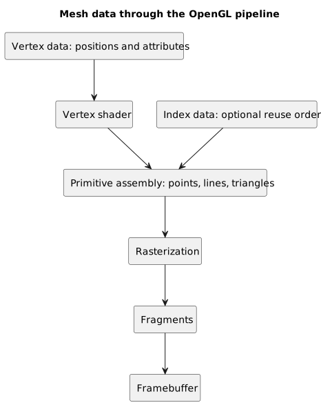
OpenGL reads vertices and indices, assembles primitives, rasterizes triangles, and produces fragments for the framebuffer.
The simplified path is:
vertex data ↓vertex shader ↓primitive assembly ↓clipping, perspective division, and viewport transform ↓rasterization ↓fragment shader ↓per-sample operations ↓framebufferThe vertices are read from buffers.
The vertex shader processes each vertex.
OpenGL then assembles the primitives.
If we selected GL_TRIANGLES, the vertices are grouped into triangles.
The primitives then pass through clipping and the transformations that take them into window space. Those that survive are rasterized, meaning they are used to generate fragments for the covered areas.
The fragment shader produces output values for those fragments, often one or more colors.
Finally, after the last tests and operations, the result may be written to the framebuffer.
This is still a simplified map: some stages are optional, and per-sample operations include tests, masks, blending, and other operations. For our purposes, however, it is enough to connect geometry with the values stored in the framebuffer.
Why One Triangle Produces Many Fragments
A triangle is defined by three vertices.
When drawn on the screen, however, it may cover many pixels.
Rasterization must determine which parts of the screen are covered by the triangle.
For the covered samples, it produces fragments to process.
Three vertices can therefore generate hundreds, thousands, or millions of fragments, depending on the triangle's size on the screen, the sampling configuration, and any overdraw.
This is a fundamental transition.
The number of vertices is not the same as the number of pixels or samples involved.
An enormous triangle may have only three vertices while covering almost the entire screen.
A highly detailed but distant model may have many vertices while covering only a few screen samples.
This distinction also helps us understand some performance problems: sometimes the cost lies in vertex processing, while at other times it lies in fragment processing.
OpenGL Example: Three Points, a Line, and a Triangle
Imagine that we have three vertices:
float vertices[] = {-0.5f, -0.5f, 0.0f, 0.5f, -0.5f, 0.0f, 0.0f, 0.5f, 0.0f};With the same data, we can obtain different results simply by changing the draw call's mode parameter.
Points:
glDrawArrays(GL_POINTS, 0, 3);Lines:
glDrawArrays(GL_LINE_LOOP, 0, 3);Triangle:
glDrawArrays(GL_TRIANGLES, 0, 3);The same vertices can therefore be interpreted in different ways.
This shows us something important: the data alone is not enough. We must also tell OpenGL how to interpret it.
Analyzing the Example
In the point case, OpenGL draws three separate primitives.
In the closed-line case, OpenGL connects the vertices to create an outline.
In the triangle case, OpenGL creates a filled surface.
Therefore:
same vertices + different primitive mode = different resultThis is why a draw call contains a parameter such as GL_TRIANGLES.
We are not simply saying, “draw this data.”
We are saying:
Interpret this data as triangles.
Common Mistakes
Thinking That a 3D Model Is a Continuous Shape
Many models are approximations made of triangles.
Even a smooth-looking surface can consist of many flat faces.
Confusing a Point with a Vertex
A point is a position.
A vertex can contain a position and other attributes.
Thinking That the Triangle Is Only a Teaching Tool
The triangle is not merely OpenGL's first example. It is a fundamental primitive in rasterized graphics.
Duplicating Vertices Without a Reason
This may not matter for simple objects, but with large meshes it is worth using indices whenever data can genuinely be shared.
Thinking That a Shared Position Means a Shared Vertex
Two vertices can occupy the same position but have different attributes, such as different normals or texture coordinates.
Ignoring the Winding Order
Vertex order determines the front face and back face, so it affects culling. If we calculate geometric normals using a cross product, it also affects their direction.
Confusing a Mesh with a Complete Model
A mesh describes geometry and topology. A model may also contain materials, textures, animations, and hierarchies.
Thinking That More Triangles Are Always Better
More triangles may increase detail, but they also increase cost. Quality also depends on shading, textures, normals, and distance from the camera.
Frequently Asked Questions
Why Not Use Squares Directly?
Because quadrilaterals can become ambiguous if their four vertices do not lie on the same plane. Triangles are planar and simpler to manage. In addition, the modern OpenGL core profile does not expose a quadrilateral primitive, so we must triangulate them before rendering.
Does a Triangle Always Have to Be Visible?
No. It may be degenerate, lie outside the visible volume, be discarded during clipping, removed by culling, occluded by the depth test, or rejected by other tests and masks.
Does a Mesh Contain Only Triangles?
It depends on the context. In modeling software, a mesh may contain other polygon types. For rasterized rendering, however, it is often converted to triangles.
Is Every Vertex Unique?
No. Two vertices may occupy the same position but have different attributes. From the rendering system's perspective, they are distinct vertices.
Why Use Indices?
To reuse complete vertices, including all their attributes, and reduce duplication when that data is genuinely shared. This is particularly useful in complex meshes.
What Does It Mean to Rasterize a Triangle?
It means determining which screen samples the triangle covers and generating the fragments that need to be processed.
Is the Triangle Always Drawn by the GPU?
In common hardware-accelerated implementations, the CPU prepares data and commands while the GPU executes much of the graphics pipeline. The OpenGL specification, however, defines the behavior of the API and does not require a physical GPU: software implementations also exist.
Mini Exercise
Try to answer the following questions.
- What is the difference between a point and a vertex?
- Why are three vertices enough to define a triangle?
- Why is a square often divided into two triangles?
- How many triangles are needed to represent the 6 faces of a cube?
- What does
GL_TRIANGLESdo? - Why can indices reduce vertex duplication?
- What is the winding order?
- Why can a triangle with only three vertices generate many fragments?
Quick answers:
1. A point is a position. A vertex can contain a position and other attributes.2. Three non-collinear points bound a flat triangular surface.3. Because the GPU works well with triangles, and a triangle is a simple, unambiguous primitive.4. 12 triangles, because each square face can be divided into 2 triangles.5. It tells OpenGL to interpret every group of three vertices as a triangle.6. Because they allow multiple triangles to use the same complete vertices.7. It is the order in which a triangle’s vertices are specified, such as clockwise or counterclockwise.8. Because the triangle may cover many screen samples during rasterization.Conclusion
We have seen that 3D graphics does not begin directly with the final pixels, but with a geometric description of the scene.
That description uses simple elements: points, lines, vertices, triangles, and meshes.
A point indicates a position. A vertex associates other attributes with that position. A line segment connects two vertices. A triangle bounds a surface. A mesh organizes vertices and faces to represent complex shapes.
The triangle is central because it is simple, planar, easy to interpolate across, and well suited to the graphics pipeline. Even complex objects such as cubes, houses, characters, and environments can be represented as collections of triangles.
In OpenGL, this data is read from buffers, processed by the vertex shader, and assembled into primitives. After clipping and the final transformations, the primitives are rasterized into fragments; the fragment shader and per-sample operations then determine which values reach the framebuffer.
In short:
mesh → vertices → primitives → fragments → framebuffer → imageIn the next article, we will move from geometry to the role of OpenGL itself. We will see why OpenGL is not a graphics engine, not a GPU, and not a magical library, but an API built around specifications, drivers, and state.
Sources and References
- Khronos, OpenGL 3.3 Core Profile Specification, the normative reference for the OpenGL 3.3 core pipeline and state.
- OpenGL Wiki,
Primitive, for the assembly of points, lines, triangles, and triangle strips. - OpenGL Wiki,
Face Culling, for winding order, front faces, and the initial culling state. - OpenGL Wiki,
Rendering Pipeline Overview, for the main stages of the pipeline. - Khronos Reference Pages,
glDrawArrays, for non-indexed rendering. - Khronos Reference Pages,
glDrawElements, for indexed rendering and the meaning of the offset. - Khronos Reference Pages,
glFrontFaceandglCullFace, for face and culling configuration. - Cover image: Rendering techniques example, rasterization, low quality, Blender EEVEE by KaiaVintr, Wikimedia Commons, licensed under CC BY-SA 4.0. Image cropped and converted to WebP for the site layout.

Last updated
2026-07-07.
Article source content/blog/opengl_points_lines_triangles_meshes.