Abstract
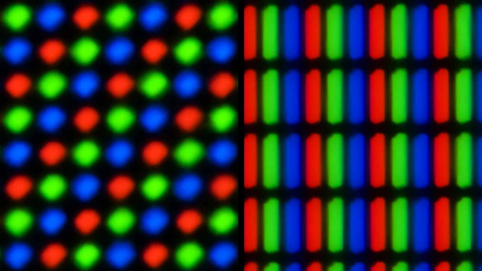
In the first article, we saw that computer graphics is, in essence, the process of transforming data and calculations into visible images. We now need to take a closer look at what a digital image actually is.
When we look at a photograph on a computer, a texture applied to a 3D model, or the result of a scene rendered with OpenGL, we are looking at a grid of small colored elements: pixels.
The idea seems simple. Behind that apparent simplicity, however, lie several important concepts: dimensions, resolution, color channels, bit depth, alpha, textures, framebuffers, and the numerical representation of color.
Without these foundations, OpenGL becomes more difficult to understand. At the end of the pipeline, the GPU must produce values that can be written to a rendering destination and, in the case of the framebuffer associated with a window, displayed on the screen.
Let us therefore examine pixels, colors, and digital images, beginning with a simple mental model and gradually connecting it to OpenGL.
Why This Topic Matters
When studying OpenGL, we tend to begin with triangles, shaders, and buffers.
That is understandable. They are the most visible parts of the process: we write code, prepare vertices, call glDrawArrays, and hope to see something in the window.
The final result of all that work, however, is always an image.
Even a complex 3D scene filled with models, lights, textures, shadows, and materials must eventually become a grid of colors.
This means that every graphics concept eventually returns to one question:
What color should this point on the screen have?
Modern computer graphics may seem far removed from this question because it deals with three-dimensional objects, matrices, shaders, pipelines, and GPU memory. The final result, however, remains a collection of color values.
For this reason, it is worth pausing for a moment to understand what a digital image really is.
The Simple Idea: A Mosaic of Colored Tiles
Imagine a large mosaic.
Up close, we can see many small tiles. Each tile has a color. Some are red, others blue, green, black, or white.
If we look at the mosaic from very close range, we can distinguish the individual tiles. If we step back, however, our eyes begin to combine those small elements and perceive a complete image.
A screen works in a similar way, at least as a mental model.
We can imagine a raster image as a large table of small colored elements. Each element is called a pixel.
A pixel is not “the image.” It is one individual point in the image.
A single tile is not the mosaic, but the mosaic exists because many tiles have been arranged in a particular order.
In the same way, a raster image exists because many pixels have been arranged according to a precise structure.
What Is a Pixel?
The word pixel comes from “picture element.”
A pixel is the smallest addressable element of a raster image.
In simpler terms, it is one cell in the image grid.
In our simplified model, every pixel is associated with at least two important pieces of information:
- a position;
- one or more values, such as those representing its color.
The position tells us where the pixel is located in the grid.
The associated values describe how it should appear or what information it should store.
If we have a very small image, for example 4x4, we can imagine it like this:
[red] [red] [red] [red][red] [white] [white] [red][red] [white] [white] [red][red] [red] [red] [red]This image has 4 columns and 4 rows. It therefore contains:
4 × 4 = 16 pixelsA real photograph may contain millions of pixels, but the principle is the same.
Only the quantity changes.
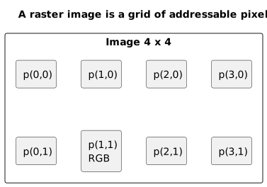
A raster image is a grid: each pixel has a position and stores numerical values, often used to represent color.
Dimensions and Resolution
In everyday language, we often use resolution to describe how many pixels make up an image. More precisely, 1920x1080 describes its dimensions in pixels:
- 1920 pixels wide;
- 1080 pixels high.
The word resolution can also refer to pixel density, measured in units such as PPI; in printing, we often encounter DPI as well. For simplicity, this article will mostly use “resolution” in the first sense.
We calculate the total number of pixels by multiplying width by height:
1920 × 1080 = 2,073,600 pixelsA Full HD image therefore contains more than two million pixels.
A 4K UHD image with dimensions of 3840x2160 contains:
3840 × 2160 = 8,294,400 pixelsThat is more than eight million pixels. The label 4K may refer to other formats as well; 3840x2160 more precisely identifies 4K UHD.
This figure matters because every pixel requires memory and may add to the amount of work performed during rendering.
Increasing the resolution does not automatically mean that an image will “look better.” First and foremost, it increases the amount of data and the work required to produce the image. The detail we can actually perceive also depends on the content, the display size, and the pixel density.
Resolution and Detail
A higher resolution makes it possible to represent more detail.
If we draw a diagonal line on a very small grid, the line will appear stair-stepped. If the grid is much denser, those steps become less noticeable.
This happens because a raster image must approximate continuous shapes using discrete pixels.
The computer cannot color “half of an ideal point” on an infinitely precise grid. It must choose values for real pixels.
This simple limitation gives rise to many familiar graphics problems:
- jagged edges;
- aliasing;
- loss of detail;
- blurry images;
- textures with inadequate resolution;
- the need for filtering and anti-aliasing techniques.
We will not explore these topics in detail yet. It is useful, however, to recognize that many advanced subjects begin with a simple problem: we are representing continuous shapes within a finite grid.
Aspect Ratio
In addition to pixel dimensions, the aspect ratio - the relationship between width and height - is important.
An image measuring 1920x1080 has an aspect ratio of 16:9.
Indeed:
1920 / 1080 ≈ 1.777...16 / 9 ≈ 1.777...An image measuring 1024x1024 has an aspect ratio of 1:1, so it is square.
Why does this matter?
If we ignore the aspect ratio during resizing or projection, an image or scene may appear distorted.
A circle may become an ellipse. A square may look like a rectangle. A 3D scene may appear compressed or stretched.
In OpenGL, this will become important when we discuss the viewport, projection, and the camera.
Color as Numerical Information
To us, color is a perception.
We say “red,” “blue,” “green,” “yellow,” and “purple.”
A computer, however, must represent color using numbers.
One of the most common models is RGB.
RGB stands for:
R: red;G: green;B: blue.
The idea is that many colors can be represented by combining different amounts of red, green, and blue. The precise meaning of those combinations, however, depends on the color space being used, such as sRGB.
In a common 8-bit-per-channel format, each component can have a value from 0 to 255.
Examples:
Black = (0, 0, 0)White = (255, 255, 255)Red = (255, 0, 0)Green = (0, 255, 0)Blue = (0, 0, 255)Yellow = (255, 255, 0)Cyan = (0, 255, 255)Magenta = (255, 0, 255)Black has every component set to zero.
White has every component set to its maximum value.
Yellow combines red and green.
Magenta combines red and blue.
Cyan combines green and blue.
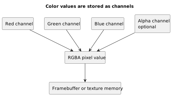
A pixel can be represented as a set of channels: red, green, blue, and, when needed, alpha.
Why Red, Green, and Blue?
Displays normally use additive color synthesis.
In simple terms, we begin with darkness and add light.
By turning on red, green, and blue light at different intensities, we can produce many colors.
This differs from painting on paper, where we often think in subtractive terms: by mixing pigments, we absorb certain components of light and reflect others.
The RGB model is natural for displays because each pixel can be composed of red, green, and blue light-producing components.
We should not, however, confuse the RGB model with the full complexity of human color perception. Color is a much broader phenomenon involving the physics of light, the biology of the eye, and the color space in use. For learning OpenGL, however, RGB remains an excellent starting point.
From 0--255 to 0.0--1.0
In common 8-bit-per-channel image files, we often find integer values between 0 and 255.
In OpenGL and shaders, we will often work with normalized floating-point components between 0.0 and 1.0.
Pure red can therefore be written like this:
8-bit RGB: (255, 0, 0)Normalized RGB: (1.0, 0.0, 0.0)White:
8-bit RGB: (255, 255, 255)Normalized RGB: (1.0, 1.0, 1.0)Black:
8-bit RGB: (0, 0, 0)Normalized RGB: (0.0, 0.0, 0.0)The conversion is straightforward:
normalized_value = 8_bit_value / 255.0For example:
128 / 255.0 ≈ 0.502An 8-bit value of 128 therefore corresponds to approximately 0.5.
This normalization is convenient in shaders because it allows us to treat colors as numerical vectors.
For example, we can write a color in GLSL like this:
vec3 color = vec3(1.0, 0.5, 0.2);Or include alpha:
vec4 color = vec4(1.0, 0.5, 0.2, 1.0);Color Channels
A channel is one component of the color information.
An RGB image has three channels:
- red;
- green;
- blue.
An RGBA image has four channels:
- red;
- green;
- blue;
- alpha.
We can imagine each channel as a separate sheet.
The first sheet records how much red each pixel contains.
The second records how much green it contains.
The third records how much blue it contains.
The computer then combines these sheets to produce the final image.
For example, an RGBA pixel can be represented like this:
R = 255G = 128B = 0A = 255In normalized form:
R = 1.0G ≈ 0.5B = 0.0A = 1.0In the simplified model we have used so far, this pixel represents a fully opaque orange.
Alpha: Opacity and Transparency
The alpha channel is often used to represent the opacity or coverage of a color.
By convention, an alpha value of 1.0 usually indicates a fully opaque color, while 0.0 indicates a fully transparent contribution. An intermediate value such as 0.5 represents a partial contribution.
For example:
vec4 transparentRed = vec4(1.0, 0.0, 0.0, 0.5);This may represent a semi-transparent red.
There is, however, an important point to clarify: alpha is only a fourth numerical component. Its practical meaning depends on how we interpret it, and having an alpha value does not automatically produce correct transparency on the screen.
In OpenGL, we need to configure blending to combine a source color with the color already stored in the framebuffer.
Later, for example, we will encounter functions such as:
glEnable(GL_BLEND);glBlendFunc(GL_SRC_ALPHA, GL_ONE_MINUS_SRC_ALPHA);For now, the general idea is enough: alpha is additional information that can be used to control how a color combines with what has already been drawn. Several alpha representations and blending methods exist, and we will examine them later.
Bit Depth
When we say that an image uses 8 bits per channel, we mean that each channel can represent 256 distinct values.
Why 256?
Because 8 bits can represent:
2^8 = 256 valuesThose values range from 0 to 255.
An RGB image with 8 bits per channel therefore uses:
8 bits for R8 bits for G8 bits for BFor a total of:
8 + 8 + 8 = 24 bits per pixelAn RGBA image with 8 bits per channel uses:
8 + 8 + 8 + 8 = 32 bits per pixelFor these specific formats, we can therefore speak of 24-bit RGB images and 32-bit RGBA images. The phrase “32-bit image” by itself, however, may refer to different representations. It is always better to specify the format and the number of bits per channel as well.
How Much Memory Does an Image Use?
Calculating how much memory an image occupies is a useful exercise.
Suppose we have a 1920x1080 image in an RGBA format with 8 bits per channel.
Each pixel has 4 channels:
R, G, B, AEach channel occupies 1 byte because 8 bits equal 1 byte.
Each pixel therefore occupies:
4 bytesThe total number of pixels is:
1920 × 1080 = 2,073,600 pixelsThe color data alone therefore requires:
2,073,600 × 4 = 8,294,400 bytesThat is approximately 8.29 MB, or 7.91 MiB when using binary units.
Keep in mind that this is a simple estimate for the raw image data. It does not account for mipmaps, row alignment, additional copies, or a GPU internal format other than RGBA8.
Compressed files such as PNG and JPEG may occupy less space on disk. When loaded into memory for use by the GPU, however, they often require a decompressed representation.
This distinction matters.
A small image file on disk does not necessarily become a small texture in GPU memory.
An Image on Disk and an Image in Memory
An image stored on disk may be compressed.
For example:
- PNG uses lossless compression;
- JPEG normally uses lossy compression;
- other formats use different strategies.
When we load an image for use as an OpenGL texture, however, we often decode it into a sequence of per-pixel values.
A PNG file occupying only a few kilobytes, for example, may expand to several megabytes once loaded into memory.
This distinction is fundamental:
file on disk ≠ raw data in memoryThe file on disk is an encoded container.
The data in memory is a representation that the program can process and transfer to OpenGL.
When we use a conventional 2D image as a texture, we will need to load the file, decode it, and then transfer the data to OpenGL, for example with glTexImage2D.
GPU-supported compressed texture formats also exist. “Texture in memory” does not therefore always mean “uncompressed RGBA,” although that remains the simplest case to study at first.
Raster and Vector Images
So far, we have discussed raster images.
A raster image is represented as a grid of pixels.
Examples include:
- photographs;
- screenshots;
- many textures;
- PNG images;
- JPEG images;
- results read from a framebuffer.
A vector image, by contrast, describes shapes using mathematical elements:
- lines;
- curves;
- circles;
- polygons;
- fills.
An SVG file, for example, might describe a circle like this:
center = (x, y)radius = rcolor = redThe advantage of vector images is that they can be scaled without losing quality because the shapes are recalculated.
A raster image, by contrast, reveals its pixels when enlarged too far.
In computer graphics, we will use both ideas, although at different stages.
When we draw triangles, OpenGL processes geometric primitives described by vertices. Rasterization then transforms those primitives into fragments, and the visible result is a raster image. We should therefore avoid confusing OpenGL primitives with vector image formats, even though both begin with geometric descriptions.
Textures
In the most intuitive case, a texture is an image used as graphics data. More precisely, an OpenGL texture is a resource organized in one, two, or three dimensions that shaders can sample.
A texture can contain colors, depth information, or other numerical values. It may be applied to a surface, used as a lookup table, attached to a framebuffer as a rendering destination, or employed in many other ways.
In the simplest case, we can imagine a texture as a sticker placed on a triangle or a 3D model.
To draw a realistic wall, for example, we could use an image of bricks instead of coloring the wall with one uniform shade of brown.
The texture contains the visual detail.
The geometry determines where the wall is located.
The shader decides how to combine the texture, lighting, and other data.
Textures will become a central topic later in the series.
For now, a simple model is enough: a 2D texture can contain a digital image that the GPU will sample.
Image Coordinates and Texture Coordinates
We can access a raster image using coordinates expressed in pixels.
For example:
pixel at column 10, row 20An OpenGL texture is often sampled using normalized coordinates, commonly called UV coordinates. In OpenGL terminology, we also encounter the names s and t.
These coordinates typically range from 0.0 to 1.0.
In one conventional mapping, we might assign them like this:
u = 0.0 → left sideu = 1.0 → right sidev = 0.0 → bottom sidev = 1.0 → top sideThis orientation is not, however, a universal property of an image file. It depends on how we arrange the data in memory and assign coordinates to the vertices. For this reason, when we begin loading textures, we may need to flip either the image or the coordinates vertically.
Normalized coordinates are convenient because they allow us to apply the same image to surfaces of different sizes.
Instead of saying “take the texel at column 123,” we say “take the point 25% across the width and 70% up the height.”
The shader then uses these coordinates to sample the texture.
Filtering: When One Texel Is Not Enough
Suppose we have a small texture and apply it to a large square.
Each texel, meaning each element of the texture, must contribute to many pixels on the screen.
What should OpenGL do?
It can select the nearest texel. The image will appear very sharp, but also blocky.
Alternatively, it can combine values from nearby texels. The image will appear smoother, although it may become blurry.
Texture filters control these behaviors.
Later, we will discuss:
GL_NEAREST;GL_LINEAR;- mipmaps;
- minification;
- magnification.
Mipmaps mainly address the opposite situation, minification, in which a highly detailed texture is projected onto a small area of the screen.
These subjects also arise from a simple question:
What happens when the texture grid does not match the screen grid?
Framebuffers
The framebuffer is one of the most important ideas connecting digital images to OpenGL.
A framebuffer defines a rendering destination.
We can imagine it as a digital sheet on which the GPU writes the result of rendering.
Conceptually, a framebuffer may provide several buffers, including:
- a color buffer;
- a depth buffer;
- a stencil buffer.
The color buffer stores final or intermediate color values.
The depth buffer stores depth information, which is useful for determining which object lies in front of another.
The stencil buffer stores values used for masks and specialized tests.
For a framebuffer we create ourselves, the actual data resides in objects attached to it, such as textures or renderbuffers. The framebuffer object primarily stores the configuration of those attachments.
When we clear the screen with OpenGL, we are actually clearing one or more buffers.
For example:
glClear(GL_COLOR_BUFFER_BIT);clears the color buffer.
When we add depth testing, we will also use:
glClear(GL_COLOR_BUFFER_BIT | GL_DEPTH_BUFFER_BIT);At the end of fragment processing, OpenGL can write the results into the buffers associated with the currently bound framebuffer.
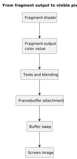
The fragment shader produces color values; tests, blending, and the framebuffer determine which values become part of the visible image.
The Default Framebuffer and Custom Framebuffers
When we create a window and its context with a library such as GLFW, the system provides a default framebuffer associated with that window.
This is commonly called the default framebuffer.
When rendering normally to the window, we use this framebuffer.
Later, however, we can create custom framebuffer objects and attach textures or renderbuffers to them.
This allows us to render into a texture instead of directly to the screen.
For example:
3D scene → texture → post-processing → screenThis mechanism makes it possible to implement effects and techniques such as:
- grayscale;
- blur;
- bloom;
- edge detection;
- rendering on mirrors or virtual screens;
- shadow mapping.
A framebuffer is therefore not simply “the screen.” It is a rendering destination.
The screen is only one possible final destination.
Clearing the Background Color in OpenGL
One of the first OpenGL functions we encounter is glClearColor.
For example:
glClearColor(0.1f, 0.2f, 0.3f, 1.0f);glClear(GL_COLOR_BUFFER_BIT);Let us examine what this means.
The first function sets the value that glClear will use to clear color buffers in the current draw framebuffer.
glClearColor(0.1f, 0.2f, 0.3f, 1.0f);The four values are:
R = 0.1G = 0.2B = 0.3A = 1.0In our RGB model, these values describe a bluish gray with an alpha value of 1.0.
The second function requests that the color buffer be cleared:
glClear(GL_COLOR_BUFFER_BIT);Here, we tell OpenGL to clear the color buffer using the value set earlier. In our initial model, we can imagine the entire rendering area being cleared, although other OpenGL state may restrict it.
glClearColor does not clear anything by itself. It only sets the clear value, with components clamped to the range 0.0–1.0.
glClear performs the clearing operation.
This distinction matters because OpenGL often behaves like a state machine: first we configure something, and then we issue a command that uses that configuration.
A Small Complete Example
Suppose we already have a working OpenGL window.
Inside the render loop, we could write:
while (!glfwWindowShouldClose(window)) { glClearColor(0.1f, 0.2f, 0.3f, 1.0f); glClear(GL_COLOR_BUFFER_BIT); glfwSwapBuffers(window); glfwPollEvents();}This program does not draw triangles. It does not use shaders or load textures.
Even so, it already produces an image: a window filled with one color.
Let us follow the process:
glClearColorsets the clear color.glClearfills the color buffer with that color.glfwSwapBuffersswaps the front and back buffers, presenting the result.glfwPollEventsprocesses pending events.
This behavior assumes a double-buffered window, which is the default configuration in GLFW.
Even an “empty window,” therefore, is not truly empty.
It contains colored pixels.
Animating Color over Time
We can make the continuous production of images more obvious by changing the color over time.
For example:
float time = static_cast<float>(glfwGetTime());float green = (std::sin(time) + 1.0f) / 2.0f;glClearColor(0.1f, green, 0.3f, 1.0f);glClear(GL_COLOR_BUFFER_BIT);Here, green changes over time.
std::sin(time) produces a value between -1.0 and 1.0. To use it, we need to include the <cmath> header.
With this expression:
(std::sin(time) + 1.0f) / 2.0fwe bring the result into the range 0.0–1.0.
The green channel therefore changes gradually, making the background color appear animated.
This is a small example, but a useful one: it demonstrates that a color is only a collection of numbers. If we change those numbers over time, the image changes as well.
The Viewport and the Rendered Image Size
In OpenGL, the viewport defines the rectangular region of the framebuffer to which the final coordinates in the pipeline are transformed.
For example:
glViewport(0, 0, 800, 600);This means:
starting x = 0starting y = 0width = 800height = 600More precisely, the viewport transformation maps normalized device coordinates to window coordinates, expressed in pixels relative to the framebuffer.
If the framebuffer changes size but the viewport is not updated, rendering may occupy only part of the available area or be clipped. To preserve the proportions of the scene, we will also need to update the projection separately using the new aspect ratio.
For this reason, we often register a callback:
void framebuffer_size_callback(GLFWwindow* window, int width, int height) { glViewport(0, 0, width, height);}When the framebuffer size changes, this callback updates the viewport as well. Using the framebuffer size rather than the logical window size is especially important on high-density displays, where the two may not match.
This detail brings us back to resolution and aspect ratio: OpenGL needs to know the pixel area into which it is rendering.
Pixels, Fragments, and Samples
So far, we have spoken mainly about pixels.
In the OpenGL pipeline, however, we will also encounter the concept of a fragment.
A fragment is not exactly the same as a pixel.
A fragment is a collection of data produced by rasterizing a primitive, such as a triangle, and represents a possible contribution to the framebuffer.
The fragment shader operates on fragments, not directly on final pixels.
Why does this distinction matter?
A fragment may:
- be discarded by the fragment shader;
- fail the stencil test or depth test;
- be combined through blending;
- cover one or more samples when multisampling is enabled;
- make no contribution to the final visible color.
A sample is a sampling location within the framebuffer. Without multisampling, we normally have one sample per pixel; with techniques such as MSAA, we may have several. Pixels, fragments, and samples are therefore related concepts, but they are not equivalent.
We can simplify the distinction like this:
pixel = an element in the image gridfragment = data produced by rasterization for a possible contributionsample = a sampling location in the framebufferThis distinction will become fundamental when we study the fragment shader.
The Final Image and Perception
A digital image consists of numbers, but we do not perceive numbers.
Our eyes and brain interpret colors, contrasts, edges, motion, depth, and brightness.
Computer graphics is therefore not only a mathematical problem. It is also a perceptual one.
For example:
- an excessively jagged edge may look artificial;
- a blurry texture may appear to lack detail;
- an incorrect color may make a scene look unnatural;
- excessive contrast may cause visual fatigue;
- a scene rendered at a low frame rate may appear choppy.
Many graphics techniques try to produce images that are not merely “numerically correct,” but also convincing to the human eye.
Connecting This to OpenGL
At this point, we can connect everything to OpenGL.
When using OpenGL, we will often work with the following concepts:
- normalized colors;
- framebuffers;
- color buffers;
- textures;
- viewports;
- fragment shaders;
- blending;
- image formats;
- RGBA channels.
Even our first colored triangle will involve several of them.
The vertex shader will calculate the final positions of the vertices.
Rasterization will produce fragments.
The fragment shader will produce one or more output values, often colors.
Tests, blending, and other fragment operations will determine which values are written to the framebuffer.
The screen will display the pixels.
In a highly simplified form, the chain looks like this:
geometry data ↓OpenGL pipeline ↓fragments ↓colors ↓framebuffer ↓buffer swap ↓visible pixelsAlthough this article discusses pixels and colors, then, it is not separate from OpenGL. It explains the foundation of OpenGL's final result.
Common Mistakes
Thinking That an Image Is Independent of Resolution
A raster image has precise dimensions in pixels.
If we enlarge it too much, either its pixels become visible or the image must be interpolated.
Confusing File Size with Memory Usage
A PNG file may be small on disk but occupy much more memory once decoded into RGBA data.
Thinking That Alpha Automatically Means Transparency
Alpha is only a component. To obtain the intended result in OpenGL, we need to interpret it correctly and, in the common transparency case, configure blending.
Using 0--255 Values in Shaders
In GLSL, when working with normalized colors, we write red like this:
vec3(1.0, 0.0, 0.0)Not like this:
vec3(255.0, 0.0, 0.0)Unless we are performing an explicit conversion and know exactly why we need it.
Forgetting the Viewport
If the viewport is not updated to match the actual framebuffer size, rendering may occupy the wrong area or be clipped.
Confusing Textures with Framebuffers
In the simplest case, a texture contains an image used as data.
A framebuffer defines a rendering destination.
We can render into a texture through a custom framebuffer, but the two concepts remain distinct.
Thinking That the Fragment Shader Always Writes the Final Pixel
The fragment shader produces one or more outputs for a fragment. Tests, masks, and blending may still affect that contribution before it modifies the framebuffer.
Frequently Asked Questions
Is a Pixel Always Square?
In everyday reasoning and most modern practical cases, we can treat pixels as square elements in a grid. Historically, and in certain specialized contexts, images can have a pixel aspect ratio other than 1:1. When beginning with OpenGL, however, assuming square pixels is reasonable.
Can RGB Represent Every Possible Color?
No. An RGB triplet acquires a precise meaning only within a color space, which is defined in part by its primaries and transfer function. Furthermore, no common device can reproduce every color perceptible to the human eye. For introductory computer graphics, however, RGB remains a very useful model.
Why Does OpenGL Often Use Values between 0.0 and 1.0?
Normalized values are convenient to interpolate, multiply, and combine. OpenGL and GLSL do not, however, require every color value to remain in that range. With floating-point formats and calculations, we can also use values below 0.0 or above 1.0.
Is Alpha the Same as Transparency?
Not exactly. Alpha is a numerical component that may represent opacity, coverage, or other information. The result depends on how it is interpreted and, for example, on the blending configuration.
Is a Texture Always a 2D Image?
No. OpenGL provides 1D, 2D, and 3D textures, cubemaps, texture arrays, and other types. A texture can also contain data that does not represent a visible image. For a first introduction, however, a 2D texture containing colors is the most intuitive case.
Is the Framebuffer the Screen?
Not necessarily. The default framebuffer is associated with the window, but we can create custom framebuffer objects and attach textures or renderbuffers to them.
Why Does a 4K Image Require So Much Memory?
Because it contains a large number of pixels. A 4K UHD image measuring 3840x2160 in RGBA8 format requires:
3840 × 2160 × 4 = 33,177,600 bytesThat is approximately 33.18 MB, or 31.64 MiB, for the base level alone. Mipmaps, additional copies, and different formats may change the actual memory usage.
Mini Exercise
Before continuing, try to answer the following questions.
- How many pixels does a
1280x720image contain? - How many bytes does a
1280x720RGBA image with 8 bits per channel occupy? - What is the difference between RGB and RGBA?
- Why do we often use color values between
0.0and1.0in OpenGL? - What does
glClearColordo? - What does
glClear(GL_COLOR_BUFFER_BIT)do? - What is the difference between a texture and a framebuffer?
- Why does a fragment not always become a final pixel?
Brief answers:
1. 1280 × 720 = 921,600 pixels2. 921,600 × 4 = 3,686,400 bytes approximately 3.69 MB or 3.52 MiB3. RGB contains red, green, and blue. RGBA adds the alpha channel.4. Because normalized values are convenient in graphics calculations.5. It sets the color used to clear color buffers.6. It clears the color buffer using the configured clear color.7. In the simplest case, a texture contains an image used as data. A framebuffer defines a rendering destination.8. Because it may be discarded, fail a test, or be combined before contributing to the final result.Conclusion
We have seen how a raster image can be represented by a data structure organized into pixels.
Each pixel contains color information, often represented through RGB or RGBA channels. The dimensions determine how many pixels make up the image, while the bit depth determines how many values each channel can represent.
We have also seen that an image stored on disk does not necessarily match the data held in memory, that a texture is a sampleable resource, and that a framebuffer defines the destination to which OpenGL can write the result of rendering.
This article may seem far removed from triangles, but it is directly connected to the graphics pipeline. Every triangle, shader, and draw call eventually contributes to producing values that may become colors inside a framebuffer.
In short:
OpenGL does not draw “magic.”It transforms data and calculations into values that become a visible imagethrough the framebuffer.In the next article, we will move from the pixel grid to geometry: points, lines, triangles, and meshes. This will be our first step toward understanding how a 3D scene is described before it becomes an image.
Sources and References
- OpenGL 3.3 Core Profile Specification, the reference specification used throughout this series.
- Khronos OpenGL Registry, for the official OpenGL and GLSL specifications and reference pages.
- OpenGL Wiki,
Rendering Pipeline Overview, for an overview of the rendering pipeline. - OpenGL Wiki,
Framebuffer Object, for framebuffers, attachments, and rendering destinations. - OpenGL Reference,
glClearColor, for the value used when clearing color buffers. - OpenGL Reference,
glClear, for clearing buffers. - OpenGL Reference,
glViewport, for the viewport transformation. - GLFW Window Guide, for framebuffer dimensions, callbacks, and events.
- GLFW Getting Started, for double buffering and
glfwSwapBuffers. - Cover image: XO screen 01 Pengo by Pengo, Wikimedia Commons, licensed under CC BY-SA 3.0. Image cropped and converted to WebP for the site layout.

Last updated
2026-06-30.
Article source content/blog/opengl_pixels_colors_digital_images.