Abstract
When we look at a video game, an animated film, a scientific simulation, or even a colored window, we are seeing the result of a precise process: a computer transforming data and calculations into images.
At first glance, it can seem almost magical. Objects, lights, shadows, colors, movement, and three-dimensional environments appear on the screen. Behind all of this, however, we find data, memory, algorithms, and hardware designed to perform a vast number of operations in parallel.
This is what computer graphics is: the collection of techniques that allow a computer to generate, modify, process, and display images.
In this series, I want to begin with the fundamentals and take nothing for granted. Before discussing OpenGL, shaders, VAOs, VBOs, framebuffers, and pipelines, we need a general map of the journey from our code to a digital image.
Let us therefore look at what computer graphics is and why it matters when learning OpenGL.
Why Start Here?
When we begin studying OpenGL, it is tempting to jump straight into the code.
We install GLFW, initialize GLAD, copy an example from a tutorial, compile the project, and try to display our first triangle. This approach may work, but it often leaves us with an uncomfortable feeling: the triangle appears, yet we do not really understand why.
The problem is that OpenGL is not a magic function that “draws things.” It is a graphics API defined by a specification: it describes functions, behavior, and rules that an implementation must follow. The Khronos OpenGL Registry contains the official OpenGL and GLSL specifications, together with approved extensions.
This means that, when we use OpenGL, we need to think across several layers:
- our program;
- the data we prepare;
- how we store that data in memory;
- the shaders we write;
- the graphics pipeline;
- the implementation and driver;
- the GPU;
- the framebuffer;
- presentation on the screen.
Without at least a general understanding of this path, every error becomes difficult to interpret. A black screen may be caused by an incorrectly configured buffer, a shader that failed to compile, an incorrect viewport, a VAO that was not made current, or the wrong draw call.
For this reason, it is worth starting with the simplest question:
What does it mean to make a computer draw an image?
The Simplest Idea: A Sheet of Grid Paper
Imagine a sheet of grid paper.
Each square can be filled with a different color. If we color only a few squares, we see a very rough shape. If the squares are numerous, tiny, and close together, however, our eyes stop distinguishing each individual square. Instead, we see a continuous image.
We can think of a screen in a similar way.
This is not a physically perfect description, since real displays may use different technologies and subpixel arrangements. As a mental model, however, it works well: a displayed raster image can be treated as a grid of small elements called pixels.
A digital image, at least in the raster case, is therefore a grid of pixels.
In the simplest model, each pixel is associated with at least two pieces of information:
- a position;
- one or more values, such as those representing its color.
The position tells us where the pixel lies within the grid. The associated values describe how it should appear or what information it should store.
If we have a 1920x1080 display, we can imagine it as a grid 1920 pixels wide and 1080 pixels high.
The total number of pixels is:
1920 × 1080 = 2,073,600 pixelsA single Full HD frame therefore contains more than two million pixels.
If a graphics program produces 60 frames per second, it has about 16.67 milliseconds to prepare and present each new image. The actual workload depends on much more than the number of pixels, but this calculation already gives us a sense of the scale involved.
Even this, in its simplest form, is computer graphics.
Not OpenGL yet. Not shaders or triangles either. But the final objective is already clear: producing colors for locations on the screen.
The Pixel Is Not the Beginning of the Process
A common mistake is to assume that computer graphics simply means coloring pixels one at a time.
In some cases, it can. For example, a program that directly edits an image may indeed operate pixel by pixel.
In modern 3D graphics, however, we usually do not begin with pixels. We begin with a description of a scene.
Instead of saying:
color this pixel redcolor this pixel bluecolor this pixel greenwe might say:
these are the positions of a triangle's verticesthis is the camerathis is the lightthis is the materialthis is the texturenow calculate the final imageThe computer must then transform a scene description into a grid of pixels.
This transformation lies at the heart of rendering.
What Does Rendering Mean?
Rendering means producing an image from data, rules, and a description of a scene.
In the simplest case, that description might be:
draw a red triangleIn a more complex 3D scene, it may include:
- 3D models;
- positions;
- rotations;
- scales;
- materials;
- textures;
- lights;
- a camera;
- shadows;
- post-processing effects.
Rendering means taking all this information and calculating the final image.
In short:
Rendering is the process that transforms data and rules into an image.
OpenGL is one of the tools we can use to describe and start this process through a well-defined pipeline. The OpenGL Wiki describes the rendering pipeline as the sequence of stages triggered by a rendering command.
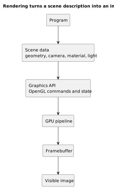
Rendering turns a scene description into commands for the graphics pipeline, then into framebuffer contents, and finally into a visible image.
Colors as Numbers
To us, color is a perception. A computer, however, needs to represent it with numerical values.
One of the most common models is RGB:
R: red;G: green;B: blue.
In a common 8-bit-per-channel format, each component can have a value from 0 to 255:
Black = (0, 0, 0)White = (255, 255, 255)Red = (255, 0, 0)In OpenGL and shaders, we will often work with normalized floating-point components between 0.0 and 1.0. The same red can therefore be written as:
Red = (1.0, 0.0, 0.0)This representation makes operations such as interpolation, multiplication, and color combination easier to express. In the next article, we will examine channels, bit depth, color spaces, and the amount of memory occupied by images in greater detail.
Alpha and Transparency
We often use RGBA rather than RGB alone.
The A stands for alpha, a component often used to represent opacity or coverage.
An RGBA color contains four values:
R, G, B, AFor example:
(1.0, 0.0, 0.0, 1.0)may represent a fully opaque red.
By contrast:
(1.0, 0.0, 0.0, 0.5)may represent a semi-transparent red.
It is important to clarify that alpha is only a numerical component: its meaning depends on how we use it. In the common transparency case, OpenGL also requires us to configure blending, which determines how the source color is combined with the color already stored in the framebuffer.
We do not need to explore the details yet. For now, it is enough to understand that transparency is also represented and processed as numerical data.
2D and 3D Graphics
2D graphics work with elements on a plane.
Examples include:
- icons;
- interfaces;
- sprites;
- text;
- maps;
- images;
- elements in a two-dimensional game.
In 2D, a position can be described using two coordinates:
x, y3D graphics add a third coordinate:
x, y, zThis third coordinate introduces another spatial axis, often associated with depth relative to the view.
A 3D point can be written as:
(1.0, 2.0, 3.0)Using an intuitive convention:
xrepresents horizontal displacement;yrepresents vertical displacement;zrepresents depth.
The actual orientation of these axes depends on the chosen coordinate system. OpenGL does not require y to always point upward or z to always point in a particular direction.
There is, however, an interesting problem: the screen is flat.
Even when we draw a 3D world, we eventually need to display it on a 2D surface. 3D graphics must therefore answer a fundamental question:
How do we transform points in three-dimensional space into pixels on a two-dimensional screen?
This question will eventually lead us to transformations, matrices, cameras, perspective projection, and clip space.
For now, we only need to recognize the problem: the world may be described in 3D, but the final image is 2D.
Models, Triangles, and Final Images
Another important distinction is the one between a 3D model and the final image.
A 3D model is not an image. It is a data structure.
It may contain:
- vertices;
- faces or indices;
- normals;
- texture coordinates;
- materials;
- animation data;
- other information.
When we look at a 3D model on the screen, we are looking at the result of rendering that model, not at the model itself.
It is a little like a recipe.
The recipe is not the cake. It describes how to make the cake. In the same way, a 3D model is not the image. It contains data that the graphics system uses to produce the image.
In rasterized 3D graphics, many models are represented using triangles. Even apparently smooth shapes, such as a sphere or a character, are often approximated by a large number of small triangles.
Triangles are simple primitives: they are always planar and straightforward to rasterize. More complex surfaces and polygons can also be divided into triangles, and graphics hardware is optimized to process them efficiently.
CPU and GPU
To understand computer graphics, we need to distinguish between at least two components:
- the CPU;
- the GPU.
The CPU is a general-purpose processor designed to handle many different kinds of work and, among other goals, to keep the latency of individual tasks low:
- program logic;
- input;
- files and networking;
- memory management;
- data loading;
- preparation of graphics commands.
The GPU, by contrast, contains many execution units and is designed to achieve high throughput across large amounts of parallel work.
This difference is fundamental.
Imagine that we need to color a large mosaic made of millions of tiles.
One person can decide on a strategy, choose the colors, and organize the work. If that person also has to color every tile alone, however, the process will take a long time.
A very large team can color many tiles at once.
The CPU is more like the person organizing the work. The GPU is more like the team performing a vast number of similar operations in parallel.
This is, of course, a simplification: CPUs also work in parallel, and GPUs are not limited to graphics. The analogy is simply meant to separate the general control of a program from the massively parallel workload typical of rendering.
During rendering, we often need to perform similar calculations for:
- many vertices;
- many primitives;
- many fragments;
- many framebuffer samples.
This is exactly the kind of work for which a GPU is well suited.
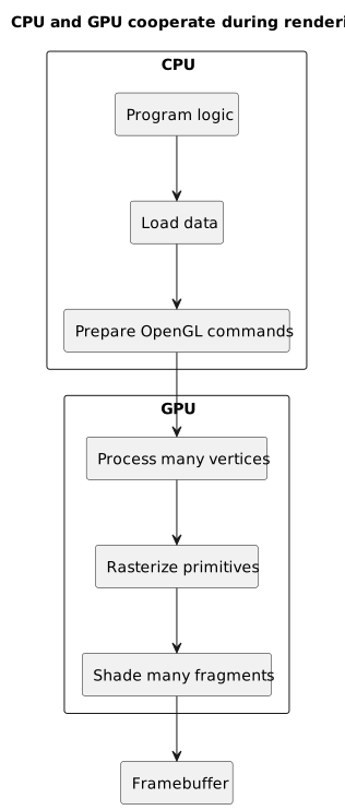
The CPU prepares data and commands; the GPU applies parallel work to vertices, primitives, and fragments before writing the framebuffer.
The Role of OpenGL
At this point, we can introduce OpenGL more precisely.
OpenGL is not the GPU.
OpenGL is not a graphics engine.
OpenGL is not a program that automatically creates a scene.
OpenGL is a graphics API specified by Khronos. Its specification defines the observable behavior of the API. Hardware vendors and software projects then provide implementations that, in the most common case, expose that behavior through a graphics driver. The official Registry contains the specifications for the API, GLSL, extensions, and related headers.
We can imagine the path as follows:
C++ program ↓OpenGL calls ↓implementation and driver ↓GPU ↓framebuffer ↓buffer presentation ↓screenOur program prepares data and calls OpenGL functions.
The implementation and driver handle those calls and organize the work for the available hardware.
In the usual case, the GPU performs most of the rendering.
The result can be written to a framebuffer and later presented on the screen. The specification does not require a particular hardware architecture, however, and software implementations also exist.
The Graphics Pipeline as an Assembly Line
We can think of the graphics pipeline as an assembly line.
Raw data enters at one end. An image comes out at the other.
A simplified version of the path we will use throughout this series looks like this:
vertices ↓vertex shader ↓primitive assembly ↓clipping, perspective division, and viewport transformation ↓rasterization ↓fragment shader ↓per-sample operations ↓framebufferEach stage has a particular task.
The vertex shader operates on vertices.
Primitive assembly interprets those vertices as points, lines, or triangles.
Clipping removes or modifies portions that lie outside the visible volume. Perspective division and the viewport transformation then move the coordinates into window space. Rasterization produces fragments in the areas covered by the primitives.
The fragment shader produces output values for those fragments, often one or more colors.
Per-sample operations include the scissor test, stencil test, depth test, blending, and write masks, among other things. These stages determine which values modify the framebuffer.
This sequence deliberately leaves out some optional stages. OpenGL 3.3, for example, also supports geometry shaders, while later versions introduce tessellation stages. For now, we only need the general map.
We will explore each stage in more detail later.
Fragments and Pixels
At this point, it is useful to introduce a distinction that often confuses beginners: a fragment and a pixel are not exactly the same thing.
A pixel is an element in the image grid.
A fragment is a set of values produced by rasterization and represents a possible contribution to the framebuffer. With multisampling, it may also include coverage information for multiple samples associated with the area of a pixel.
A sample is a sampling position associated with the framebuffer. Without multisampling, we normally have one sample per pixel; with techniques such as MSAA, we can have several.
Put more simply, when a triangle is rasterized, OpenGL produces fragments in the areas of the screen covered by that triangle. Each fragment can then be processed by the fragment shader.
Not every fragment automatically becomes a final pixel, however.
Its contribution may be discarded, combined, or prevented by several mechanisms:
discardin the fragment shader;- the scissor test;
- the stencil test;
- the depth test;
- blending;
- write masks.
Intuitively, then:
pixel = an element in the image gridfragment = a possible contribution produced by rasterizationThis distinction will become very important when we discuss rasterization, the depth buffer, and fragment shaders.
A Mental Example: Drawing a Red Triangle
Suppose we want to draw a red triangle.
As humans, we might describe it like this:
I want a red triangle in the center of the screen.A computer cannot work directly with this general statement. We need to turn it into data and instructions.
For OpenGL, the reasoning will look more like this:
These are the triangle's three vertices.This is the configuration for reading them.This is the vertex shader.This is the fragment shader.Use this data.Draw a triangle primitive.In a highly simplified form, the vertices might be:
float vertices[] = {-0.5f, -0.5f, 0.0f, 0.5f, -0.5f, 0.0f, 0.0f, 0.5f, 0.0f};These three points describe the triangle.
The red color could be produced by the fragment shader:
#version 330 coreout vec4 FragColor;void main(){ FragColor = vec4(1.0, 0.0, 0.0, 1.0);}Here, vec4(1.0, 0.0, 0.0, 1.0) means:
red = 1.0green = 0.0blue = 0.0alpha = 1.0In the simplified model used so far, this value represents a fully opaque red.
Once we have configured the required resources and made the shader program current, a draw call can start the pipeline.
What Actually Happens on the GPU?
The GPU does not, of course, “see” a triangle in the same way we do.
The GPU works with numbers.
It receives data organized in memory. It runs programs called shaders. It applies rasterization rules. It produces fragments, calculates colors, applies tests, and writes results.
If we wanted to describe the process in a highly simplified way, we could write:
1. The program prepares the vertices.2. OpenGL receives the commands.3. The driver organizes the work for the GPU.4. The GPU runs the vertex shader on the vertices.5. The vertices form a triangle.6. The triangle is rasterized.7. The fragment shader calculates the fragment output colors.8. Per-sample operations determine which values update the framebuffer.9. The window system presents the buffer intended for display.This is the path from code to pixel.
It is the path we will follow throughout the series.
Computer Graphics Is Not Only 3D
When people hear “computer graphics,” many immediately think of 3D video games.
That is understandable, but incomplete.
Computer graphics includes many fields and applications:
- 2D graphics;
- 3D graphics;
- user interfaces;
- real-time rendering;
- offline rendering;
- scientific visualization;
- simulations;
- virtual and augmented reality;
- animation and visual effects;
- digital typography;
- CAD;
- maps and GIS systems.
It also overlaps with related disciplines, such as image processing and computer vision, without being identical to them.
OpenGL is only one possible tool. Vulkan, Direct3D, Metal, WebGPU, and other systems also exist.
OpenGL remains useful for studying many fundamental concepts without immediately facing the complexity of more explicit APIs such as Vulkan. This does not mean it is always the best choice for a new product: that depends on the platform, objectives, and requirements of the project.
Real-Time and Offline Rendering
Another important distinction is the one between real-time and offline rendering.
Real-time rendering must produce images very quickly.
Examples include:
- video games;
- simulators;
- 3D interfaces;
- virtual reality;
- interactive applications.
In these cases, the system must respond immediately to the user. If we move the mouse, press a key, or reposition the camera, the image should update almost at once.
Offline rendering, by contrast, can take much longer to generate a single image.
Examples include:
- animated films;
- photorealistic architectural renderings;
- cinematic visual effects;
- images generated using computationally expensive path-tracing techniques.
In offline rendering, a single frame may take seconds, minutes, or hours to produce. In real-time rendering, we often have only a few milliseconds per frame.
OpenGL is designed primarily for interactive, real-time rendering, although it can also be used for non-interactive work or off-screen rendering.
Why Is Computer Graphics Difficult?
Computer graphics is difficult because it brings together many different subjects.
Knowing a programming language is not enough by itself.
Over time, we will encounter concepts from:
- mathematics;
- geometry;
- linear algebra;
- memory management;
- GPU architecture;
- parallel programming;
- visual perception;
- image formats;
- graphics APIs;
- debugging.
There is no need to be intimidated, however.
The solution is to proceed in layers.
First, we understand what a pixel is. Then we learn what a vertex is and how several vertices form a primitive. From there, we can examine how data reaches the GPU, how shaders process it, and how rasterization produces fragments that may contribute to the framebuffer.
Each concept can seem complicated when taken in isolation and without context. It becomes much easier to understand when placed within the complete path.
Connecting This to OpenGL
When working with OpenGL, we will often use the following mental sequence:
prepare the dataconfigure the OpenGL resourcescompile and link the shadersenter the render loopissue a draw callthe data moves through the pipelinethe result reaches the framebufferpresent the buffer on the screenTo draw our first triangle, for example, we will need to learn:
- how to create a window;
- how to create an OpenGL context and make it current;
- how to load the OpenGL entry points;
- how to create a VBO and a VAO;
- how to write and compile shaders;
- how to link them into a shader program;
- how to issue a draw call;
- how to present the result in the window.
That may seem like a lot of work for a single triangle.
And it is.
That is precisely what gives the first triangle its teaching value: it forces us to touch all the main components of the modern graphics pipeline.
Common Mistakes
Thinking That OpenGL Is a Graphics Engine
OpenGL is not Unity, Unreal Engine, or Godot.
It does not automatically manage scenes, materials, lights, models, editors, physics, or animation.
OpenGL provides a lower-level interface than these engines and does not include all of their subsystems.
Thinking That the GPU Understands Objects
The GPU does not receive “a car,” “a house,” or “a character.”
The graphics implementation receives data and commands: vertices, indices, textures, uniforms, shaders, and OpenGL state.
We are the ones who give that data meaning.
Confusing a Model with an Image
A 3D model is not the final image.
The model is a description. The image is the result of rendering it.
Confusing Fragments with Pixels
A fragment is not always a final pixel.
It is a possible contribution to the framebuffer, but it can be discarded, masked, or combined with other values.
Underestimating Memory
Graphics is not only mathematics. It is also memory.
Vertex data, textures, framebuffer attachments, and other buffers must be created, organized, and used correctly.
Looking for Code Before Understanding the Path
Copying code may make something appear on the screen, but it does not help much if we do not understand what is happening.
The goal of this series is not merely to obtain a triangle. It is to understand why that triangle appears.
Frequently Asked Questions
Are Computer Graphics and Digital Graphics the Same Thing?
It depends on the context.
“Digital graphics” is a broader expression that may refer to images created or modified using digital tools. “Computer graphics” more specifically describes the technical field concerned with generating, representing, processing, and displaying images using computers.
Is OpenGL Still Useful?
For learning the fundamental concepts behind real-time raster graphics, yes. OpenGL 4.6 remains the current desktop specification, and conformant implementations continue to be registered for recent hardware. It is not the only API available, however, nor is it always the best choice for a new and complex engine.
Support also depends on the platform and its drivers. On macOS, for example, OpenGL has been deprecated since version 10.14, and Apple recommends Metal for new projects. In this series, we will use it primarily as a cross-platform teaching tool, with OpenGL 3.3 core as our reference.
Do I Need to Know a Lot of Mathematics Before I Begin?
Not all at once.
To begin, basic coordinates, simple vectors, and some familiarity with numbers are enough. Later, we will need matrices, transformations, projections, and vector products. The important thing is to introduce them at the right time.
Why Are Triangles Used So Often?
Because they are simple and well suited to rasterization. Three non-collinear vertices define a plane, a triangle is always convex, and more complex polygons can be divided into triangles.
Does Computer Graphics Always Produce Realistic Images?
No.
Computer graphics can produce realistic, stylized, abstract, technical, scientific, or purely functional images. A user interface, a scientific chart, and a realistic video game are all different examples of computer-generated graphics.
Mini Exercise
Before moving on to the next article, try answering these questions without looking back at the previous sections.
- What is a pixel?
- Why can a color be represented by three numbers?
- What is the difference between a 3D model and the final image?
- Why is a GPU well suited to computer graphics?
- What role does OpenGL play in the path from code to screen?
- What is the difference between a fragment and a pixel?
- What does rendering mean?
If you can answer them even in simple terms, you have already understood the central idea of this article.
Conclusion
We have seen that computer graphics is not magic. It is a technical process that transforms numerical data into visible images.
A raster image can be viewed as a grid of pixels whose values are represented by numbers. In 3D graphics, however, we usually do not begin with pixels. We begin with geometric data, materials, textures, lights, and shaders. Rendering turns that description into an image.
OpenGL fits into this process as a graphics API. It allows a program to configure resources and state, issue rendering commands, and start the pipeline that carries data to the framebuffer.
In short, the journey we will follow in the next articles looks like this:
code → data → OpenGL → implementation → pipeline → fragments → framebuffer → presentation → visible pixelsUnderstanding this path is the first step toward moving beyond copied examples and beginning to understand how modern computer graphics actually works.
Sources and References
- Khronos OpenGL Registry, for the official OpenGL and GLSL specifications, extensions, and headers.
- OpenGL 3.3 Core Profile Specification, for the reference specification used throughout this series.
- OpenGL Wiki,
Rendering Pipeline Overview, for a general description of the rendering pipeline stages. - OpenGL Wiki,
Fragment, for the technical distinction between fragments, rasterization, and pixel areas. - Khronos,
OpenGL, for the API's status and general characteristics. - Khronos,
OpenGL Conformant Products, for registered conformant implementations on recent hardware. - Apple,
macOS Mojave 10.14 Release Notes, for the deprecation of OpenGL on macOS.
Image credits
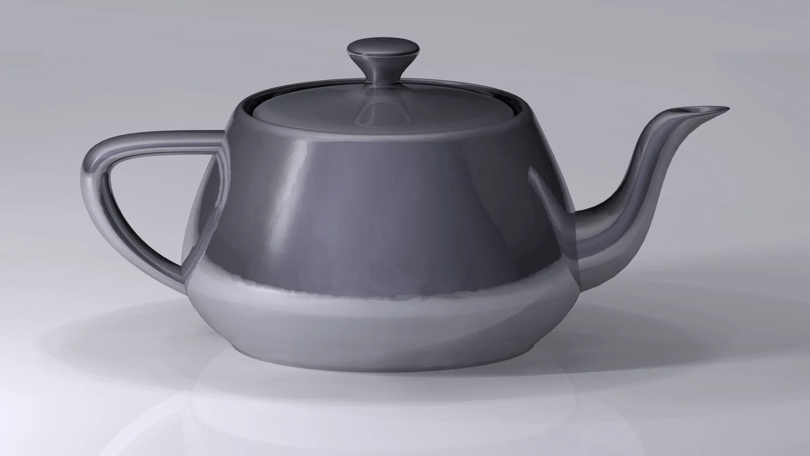
The cover image uses Utah teapot simple 2 by Dhatfield, published on Wikimedia Commons under the CC BY-SA 3.0 license.

Last updated
2026-06-23.
Article source content/blog/opengl_computer_graphics.